

Non-regular electrical stimulation patterns for treating neurological disorders
- Summary
- Abstract
- Description
- Claims
- Application Information
AI Technical Summary
Benefits of technology
Problems solved by technology
Method used
Image


Examples
example
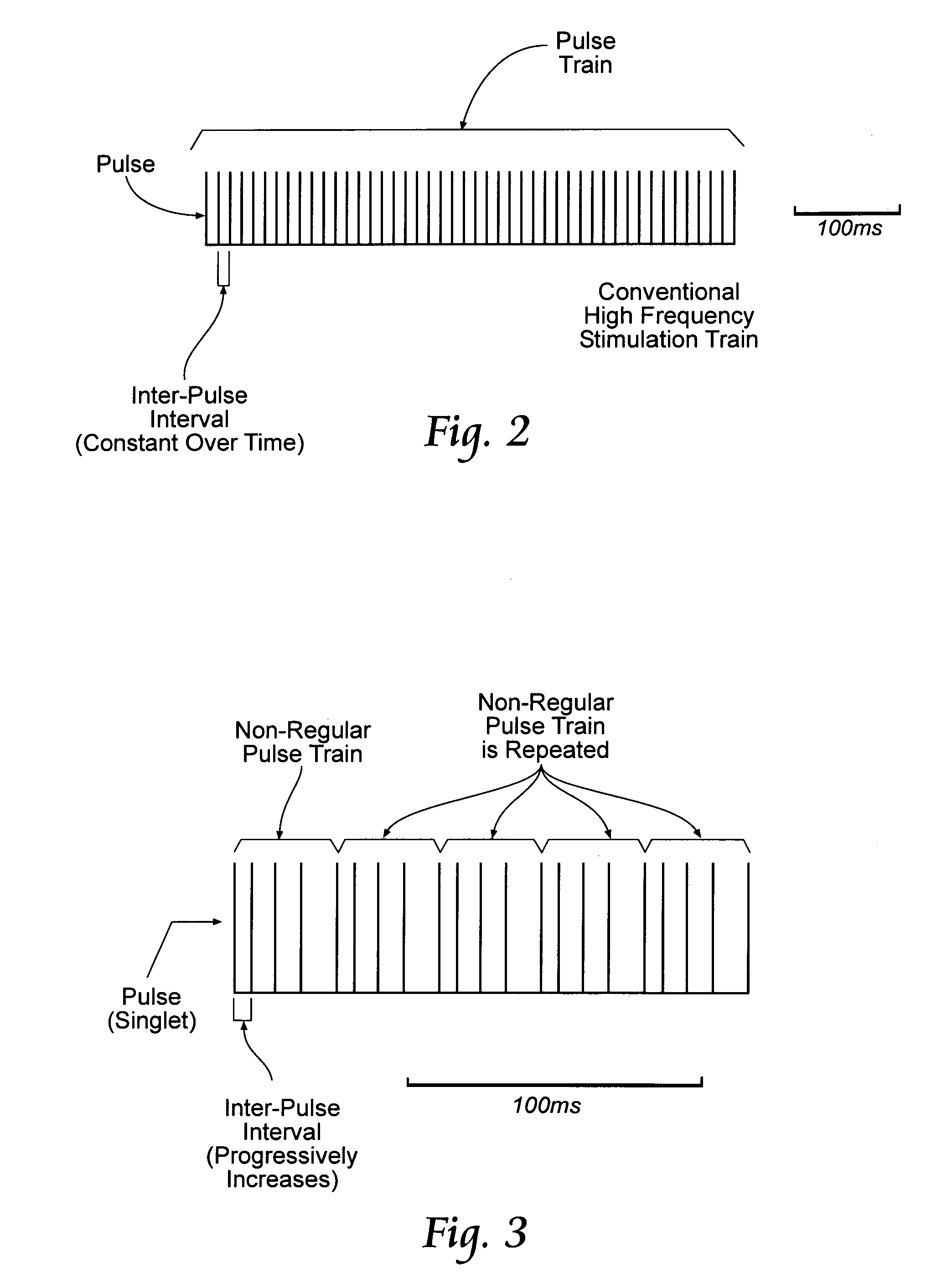
[0039]Computational models of thalamic DBS (McIntyre et al. 2004, Birdno, 2009) and subthalamic DBS (Rubin and Terman, 2004) can be used with genetic-algorithm-based optimization (Davis, 1991) (GA) to design non-regular stimulation patterns or trains that produce desired relief of symptoms with a lower average stimulation frequency than regular, high-rate stimulation. McIntyre et al. 2004, Birdno, 2009; Rubin and Terman, 2004; and Davis, 1991 are incorporated herein by reference.
[0040]In the GA implementation, the stimulus train (pattern) is the chromosome of the organism, and each gene in the chromosome is the IPI between two successive pulses in the train. The implementation can start, e.g., with trains of 21 pulses (20 genes) yielding a train length of ˜400 ms (at average frequency of 50 Hz), and the 6 s trains required for stimulation are built by serial concatenation of 15 identical pulse trains. The process can start with an initial population of, e.g., 50 organisms, constitut...
PUM
 Abstract
Description
Claims
Application Information