R-Fe-B TYPE RARE EARTH SINTERED MAGNET AND PROCESS FOR PRODUCTION OF THE SAME

a rare earth element and sintered magnet technology, applied in the field of rare earth sintered magnets based on r-fe-b, can solve the problems of not being heated sufficiently by normal resistance heating process, not easy to obtain expected crystal structure, etc., and achieve the effect of reducing remanence br, reducing the concentration of heavy rare earth elements rh, and increasing efficiency

Active Publication Date: 2010-07-22
HITACHI METALS LTD
View PDF15 Cites 33 Cited by
  • Summary
  • Abstract
  • Description
  • Claims
  • Application Information

AI Technical Summary

Benefits of technology

[0044]According to the present invention, a sintered magnet body, which has had its coercivity HcJ increased, but its remanence Br decreased, by diffusing a heavy rare-earth element RH (which is at least one element selected from the group consisting of Dy, Ho and Tb) inside the sintered magnet body through the surface thereof by evaporation diffusion process (i.e., the process performed in the step (b)), has its portion near the surface (which will be sometimes referred to herein as a “surface portion”) removed.
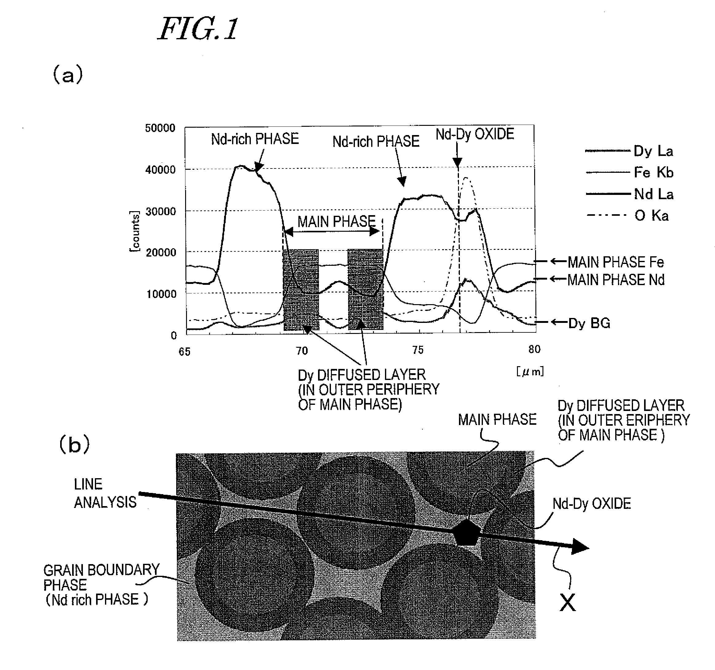
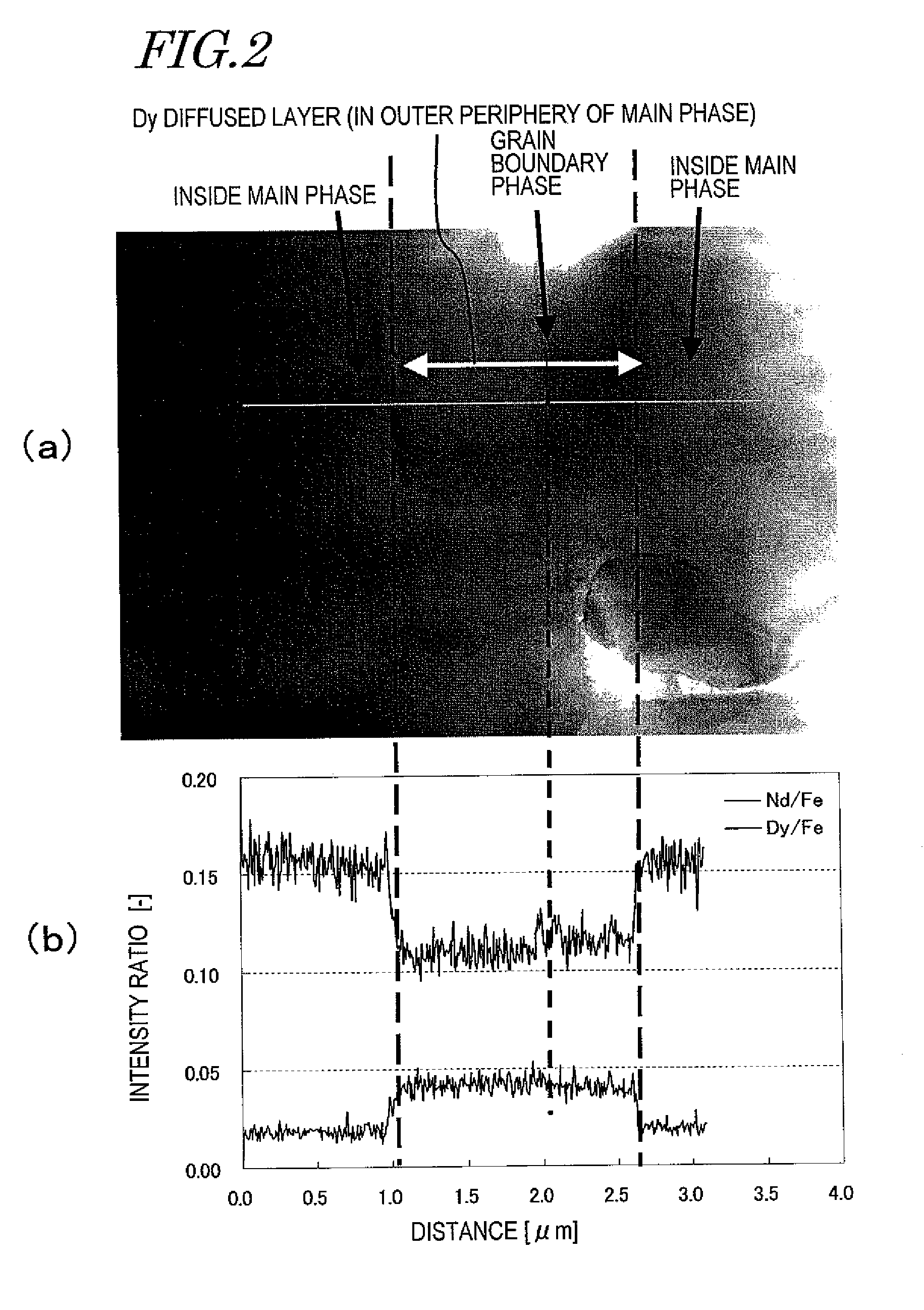
[0045]Since the sintered magnet body of the present invention includes, as a main phase, crystal grains of an R2Fe14B type compound including a light rare-earth element RL (which is at least one of Nd and Pr) as a major rare-earth element R, the heavy rare-earth element RH that has been diffused inside the sintered magnet body through its surface by the evaporation diffusion process has reached the outer periphery of the crystal grains of the R2Fe14B type compound by way of the grain boundary phase (that is an R-rich phase) of the crystal grains of the R2Fe14B type compound.
[0046]According to the evaporation diffusion process, the concentration of the heavy rare-earth element RH can be increased efficiently in the outer periphery of main phase crystal grains. In crystal grains of the R2Fe14B type compound in the surface portion of the sintered magnet body, however, the heavy rare-earth element RH tends to diffuse deeper inside, or reach closer to the core, of the crystal grains, compared to crystal grains of the R2Fe14B type compound that are located deeper than the surface portion. That is why in the surface portion of the sintered magnet body, the remanence Br will decrease more easily than deeper inside the sintered body.
[0047]According to the present invention, that surface portion of the sintered magnet body is removed after the diffusion. As will be described in detail later, according to the evaporation diffusion process, the heavy rare-earth element RH will diffuse and permeate deeper inside the sintered magnet body. That is why even if the surface portion of the magnet body was removed, the coercivity would hardly decrease compared to the magnet body that still has that surface portion. Consequently, an R—Fe—B based sintered magnet body, of which the coercivity HcJ has increased in a broader range (i.e., from the surface through the deeper region of the sintered magnet body) almost without decreasing the remanence Br compared to the sintered magnet body in which the heavy rare-earth element RH has not diffused yet, can be obtained.

Problems solved by technology

For that reason, it is not easy to obtain the expected crystal structure.
However, Dy has a boiling point of 2,560° C. According to Patent Document No. 6, Yb with a boiling point of 1,193° C. should be heated to a temperature of 800° C. to 850° C. but could not be heated sufficiently by normal resistance heating process.

Method used


Image

  • R-Fe-B TYPE RARE EARTH SINTERED MAGNET AND PROCESS FOR PRODUCTION OF THE SAME
  • R-Fe-B TYPE RARE EARTH SINTERED MAGNET AND PROCESS FOR PRODUCTION OF THE SAME
  • R-Fe-B TYPE RARE EARTH SINTERED MAGNET AND PROCESS FOR PRODUCTION OF THE SAME

Examples


embodiments

Material Alloy

[0153]First, an alloy including 25 mass % to 40 mass % of a light rare-earth element RL, 0.6 mass % to 1.6 mass % of B (boron) and Fe and inevitably contained impurities as the balance is provided. A portion of B may be replaced with C (carbon) and a portion (at most 50 at %) of Fe may be replaced with another transition metal element such as Co or Ni. For various purposes, this alloy may contain about 0.01 mass % to about 1.0 mass % of at least one additive element M that is selected from the group consisting of Al, Si, Ti, V, Cr, Mn, Ni, Cu, Zn, Ga, Zr, Nb, Mo, Ag, In, Sn, Hf, Ta, W, Pb and Bi.

[0154]Such an alloy is preferably made by quenching a melt of a material alloy by strip casting, for example. Hereinafter, a method of making a rapidly solidified alloy by strip casting will be described.

[0155]First, a material alloy with the composition described above is melted by induction heating within an argon atmosphere to make a melt of the material alloy. Next, this me...

example 1

[0182]First, as shown in the following Table 5, three alloys were prepared by strip casting process so as to have target compositions including Dy in 0 mass %, 2.5 mass % and 5.0 mass %, respectively, thereby making thin alloy flakes with thicknesses of 0.2 mm to 0.3 mm. In Table 5, every numerical data is expressed in mass %.

TABLE 5AlloyNdDyBCoCuAlFeDy 0%32.001.00.90.10.2balDy 2.5%29.52.51.00.90.10.2balDy 5.0%27.05.01.00.90.10.2bal

[0183]Next, a vessel was loaded with those thin alloy flakes and then introduced into a hydrogen pulverizer, which was filled with a hydrogen gas atmosphere at a pressure of 500 kPa. In this manner, hydrogen was absorbed into the thin alloy flakes at room temperature and then desorbed. By performing such a hydrogen process, the thin alloy flakes were decrepitated to obtain a powder in indefinite shapes with sizes of about 0.15 mm to about 0.2 mm.

[0184]Thereafter, 0.05 wt % of zinc stearate was added to the coarsely pulverized powder obtained by the hydrog...

example 2

[0199]First, using an alloy that had the composition shown in the following Table 10, thin alloy flakes D were made by strip casting process so as to have thicknesses of 0.2 mm to 0.3 mm.

TABLE 10AlloyNdDyBCoCuAlFeThin25.04.01.02.00.10.1balflakes D

[0200]Using those thin alloy flakes, sintered blocks were made by the same method as the one adopted in the first specific example described above. Then, by machining those sintered blocks, sintered magnet bodies having a length of 20 mm and a width of 20 mm and having their thickness varied from 3 mm through 7 mm in the magnetization direction were obtained as Prototypes #4, #5 and #6.

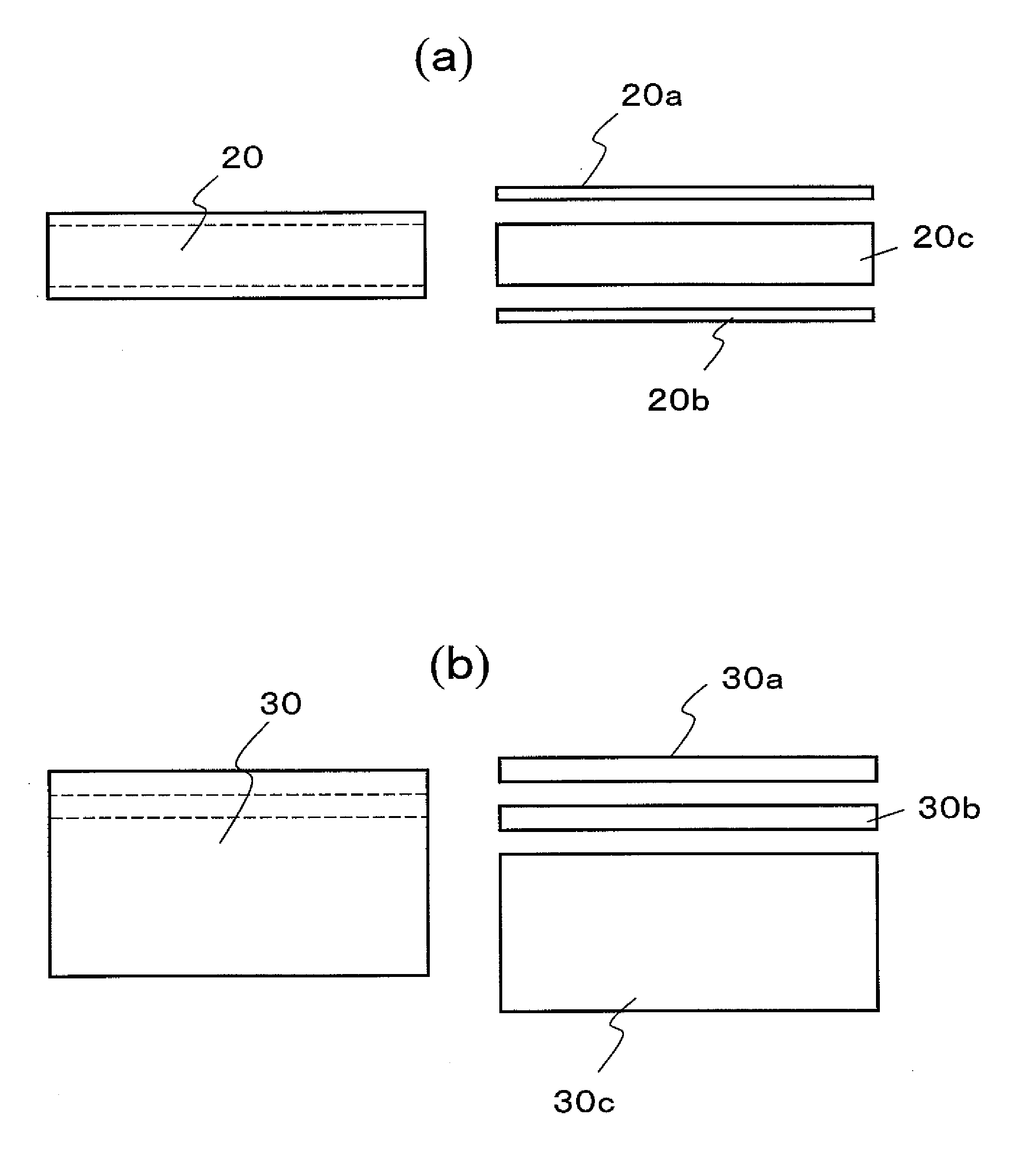
[0201]These sintered magnet bodies were acid-cleaned with a 0.3% nitric acid aqueous solution, dried, and then arranged in a process vessel with the configuration shown in FIG. 7. The process vessel for use in this preferred embodiment was made of Mo and included a member for holding a plurality of sintered magnet bodies and a member for holding two RH bulk b...


PUM

PropertyMeasurementUnit
thicknessaaaaaaaaaa
thicknessaaaaaaaaaa
thicknessaaaaaaaaaa

Abstract

In an R—Fe—B based rare-earth sintered magnet according to the present invention, at a depth of 20 μm under the surface of its magnet body, crystal grains of an R2Fe14B type compound have an (RL1-xRHx)2Fe14B (where 0.2≦x≦0.75) layer with a thickness of 1 nm to 2 μm in their outer periphery. In this case, the light rare-earth element RL is at least one of Nd and Pr, and the heavy rare-earth element RH is at least one element selected from the group consisting of Dy, Ho and Tb.

Description

TECHNICAL FIELD[0001]The present invention relates to an R—Fe—B based rare-earth sintered magnet including crystal grains of an R2Fe14B type compound (where R is a rare-earth element) as a main phase and a method for producing such a magnet. More particularly, the present invention relates to an R—Fe—B based rare-earth sintered magnet, which includes a light rare-earth element RL (which is at least one of Nd and Pr) as a major rare-earth element R and in which a portion of the light rare-earth element RL is replaced with a heavy rare-earth element RH (which is at least one element selected from the group consisting of Dy, Ho and Tb) and a method for producing such a magnet.BACKGROUND ART[0002]An R—Fe—B based rare-earth sintered magnet, including an Nd2Fe14B type compound phase as a main phase, is known as a permanent magnet with the highest performance, and has been used in various types of motors such as a voice coil motor (VCM) for a hard disk drive and a motor for a hybrid car an...

Claims


Application Information

Patent Timeline
Patent Type & Authority Applications(United States)
IPC IPC(8): H01F7/02B05D5/00
CPCB22F3/24B22F2003/248B22F2999/00C22C33/0278C22C38/005C22C2202/02H01F41/0293H01F1/0577B22F2207/01B22F2201/20H01F1/053H01F1/08H01F41/02
Inventor YOSHIMURA, KOSHIMORIMOTO, HIDEYUKIODAKA, TOMOORI
Owner HITACHI METALS LTD
Why Eureka
Try Eureka