Controlled esr low inductance capacitor

a low-inductance capacitor and capacitor technology, applied in the direction of fixed capacitors, stacked capacitors, fixed capacitor details, etc., can solve the problems of generating unacceptable voltage spikes, needing to reduce inductance becomes a serious limitation, and the potential drawback of decreasing esr may also arise, so as to reduce the overall device inductance, improve current cancellation, and increase the current path length

Inactive Publication Date: 2010-07-29
AVX CORP
View PDF35 Cites 81 Cited by
  • Summary
  • Abstract
  • Description
  • Claims
  • Application Information

AI Technical Summary

Benefits of technology

[0031]In other examples, the typically rectangular main portion of each electrode pattern used in the subject embodiments may be altered to yield multiple substantially parallel portions in which current ultimately flows in opposing directions to improve current cancellation (thus lowering overall device inductance) while simultaneously increasing current path lengths (thus increasing amounts of cont...

Problems solved by technology

As switching speeds increase and pulse rise times decrease in electronic circuit applications, the need to reduce inductance becomes a serious limitation for improved system performance.
Even the decoupling capacitors, which act as a local energy source, can generate unacceptable voltage spikes: V=L (di/dt).
As ESL has decreased in some multilayer capacitors, a potential drawback of decreasing the ESR may also arise.
In some instances, undesirable effects have been observed in the final circuits in which they are used, including mismatching of impedances, undesirable introduction of signal reflect...

Method used


Image

  • Controlled esr low inductance capacitor
  • Controlled esr low inductance capacitor
  • Controlled esr low inductance capacitor

Examples


embodiment 200

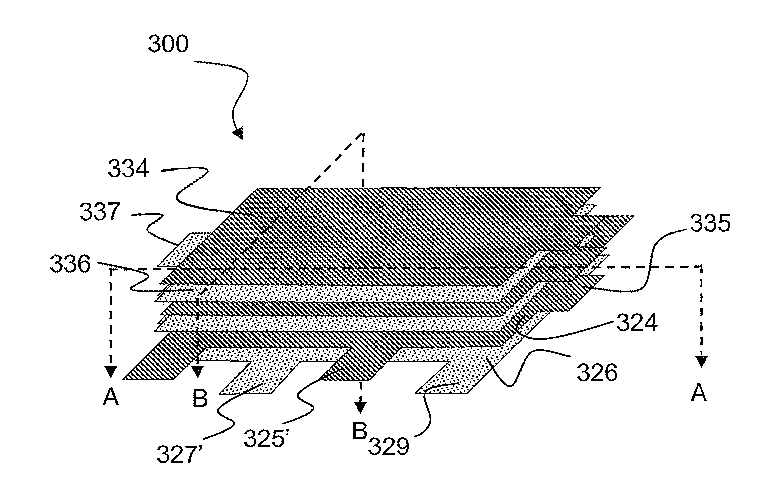
[0080]FIG. 2c provides two cross-sectional views of first exemplary capacitor embodiment 200 namely, a longitudinal cross-section on the left and a transverse cross section on the right. From the longitudinal cross-section of FIG. 2c, it is apparent that each of the first and second electrodes 224 and 226 (i.e., mother electrodes) as well as third and fourth electrodes 234 and 236 (i.e., daughter electrodes) extends to and is exposed along one of two end surfaces by an internal-connection end tab 235, 237, 225 or 227. From the transverse cross-sectional view of FIG. 2c, it is apparent that only the first and second electrodes 224 and 226 (i.e., mother electrodes) include directly connected tabs (225′ and 227′) that extend to and are exposed along the two side surfaces of the device 200. Areas 240 in the respective cross-sectional views generally correspond to the dielectric material provided between the various electrode layers and anchor tabs.

[0081]It should be appreciated that dif...

exemplary embodiment 200

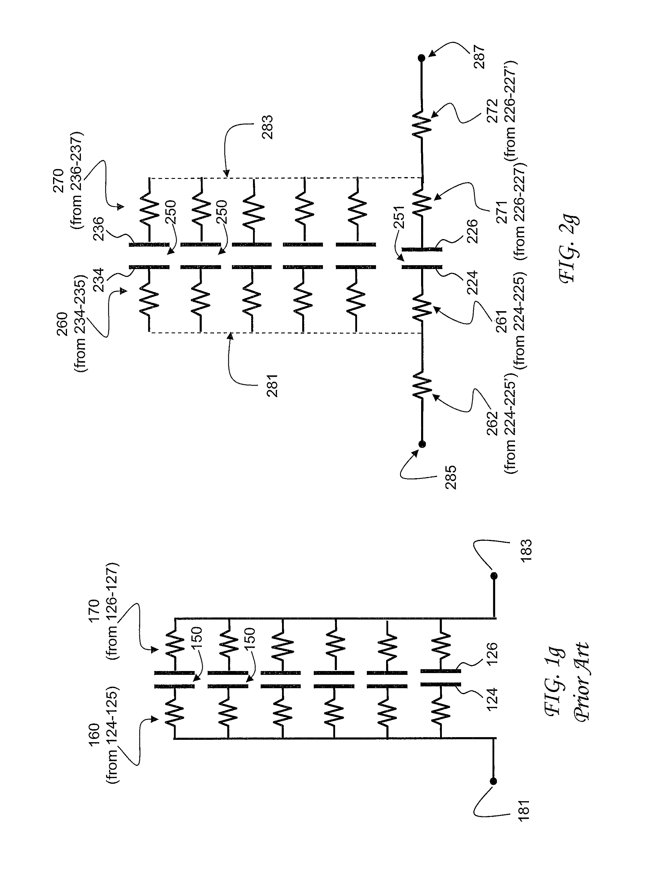
[0087]A notable present aspect of the first exemplary embodiment 200 of FIGS. 2a-2f is that the interdigitated electrode tabs 225′, 227′ (i.e., circuit-connection tabs) electrically connect the side terminations (circuit-connection terminals) only to the bottom two electrode surfaces (the pair of first and second mother electrodes 224 and 226). Since the inductance is primarily determined by the closest planes to the circuit board, such device 200 is thus a low inductance capacitor. External circuit connection is only made directly to the lower two layers, first and second electrodes 224 and 226). The rest of the electrode stack, consisting of electrode designs 234 and 236, are connected together in parallel (via the end terminations 281 and 283) but are only connected in series to the ends of electrodes 224 and 226, respectively. Electrical connection is only made internally to the third and fourth electrodes 234 and 236. By providing a large number of pairs of third and fourth (da...

exemplary embodiment 500

[0104]Referring now to FIGS. 5a through 5h, a third exemplary embodiment 500 of the present technology provides not only low inductance features, but also a way to add controlled ESR into a unitary MLC device. More particularly, and similar to the embodiments 200 and 300 described before, such exemplary device 500 utilizes not only two different electrode configurations, but four two mother electrode and two daughter electrode configurations. First and second electrodes 520 and 522 are similar in many respects to the electrodes 420 and 422 of FIGS. 4a-4c.

[0105]Referring more particularly to FIG. 5a, first electrode 520 includes a substantially rectangular main portion and two tabs 521, 521′ that extend from a longer side of the electrode 520. Second electrode 522 includes a substantially rectangular main portion and two tabs 523, 523′ that extend from the same longer side of the electrode 522 (as do tabs 521, 521′ extend from electrode 520). First electrode 520 and second electrode...


PUM


Abstract

Multilayer capacitors incorporate both low inductance (ESL) and controlled Equivalent Series Resistance (ESR) features into a cost-effective unitary device. Internal electrode patterns generally include one or more pairs of mother electrodes adapted for external connection (e.g., to a circuit, another electrical component, circuit board, or other mounting environment), and multiple pairs of daughter electrodes adapted only for internal connection to other electrodes (e.g., other daughter electrodes and/or selected mother electrodes) without direct connection to an external circuit. Mother and daughter electrodes are interdigitated with electrode tab features, where daughter electrodes have internal-connection tabs, and mother electrodes have both internal-connection tabs and circuit-connection tabs, all of which are connected to respective internal-connection or circuit-connection terminals. ESR is increased by the parallel connection between mother and daughter electrodes as well as other optional features such as but not limited to resistive terminations, resistive connectors, serpentine terminations and increased current path lengths.

Description

PRIORITY CLAIM[0001]This application claims the benefit of previously filed U.S. Provisional Patent Application entitled “CONTROLLED ESR LOW INDUCTANCE CAPACITOR,” assigned U.S. Ser. No. 61 / 147,792, filed Jan. 28, 2009, and which is incorporated herein by reference for all purposes.FIELD OF THE INVENTION[0002]The present subject matter generally concerns improved multilayer ceramic capacitors (MLCCs). More particularly, the present subject matter relates to capacitor configurations and related methodologies for making capacitors that incorporate both low inductance (ESL) and controlled Equivalent Series Resistance (ESR) features into a cost-effective unitary device.BACKGROUND OF THE INVENTION[0003]The diversity of modern technical applications creates a need for efficient electronic components and integrated circuits for use therein. Capacitors are a fundamental component used for filtering, decoupling, bypassing and other aspects of such modern applications which may include wirele...

Claims


Application Information

Patent Timeline
IPC IPC(8): H01G4/228H01G4/06B05D5/12
CPCH01G4/012H01G4/30H01G4/232
Inventor GALVAGNI, JOHN L.BEROLINI, MARIANNERITTER, ANDREW P.
Owner AVX CORP
Why Eureka
Try Eureka