[0024]Embodiments of the present disclosure provide an irradiation
system and method wherein the X-ray flux generation area of a substantially planar source is substantially equal to the
proximate target surface area facing X-ray flux generation area of the materials passing through the irradiator. The
system utilizes one or more substantially planar X-ray source(s), which generates
high intensity X-ray flux over a large area. As this X-ray flux generation area is substantially planar, the X-ray flux remains substantially uniform within the irradiation chamber. One or more
flat panel X-ray sources are placed around the irradiation chamber to generate X-ray flux. The design of the present disclosure provides a compact, efficient and safe irradiation system.
[0025]Embodiments of the present disclosure provide a safe, economical and efficient panoramic X-
ray irradiation system that offers significant advantages over prior art approaches. More specifically, present disclosure provides a system for X-
ray irradiation wherein the X-ray flux generation area of a source is substantially equal to the
proximate facing surface area of the material as it is transported through the irradiation section of the irradiator. The irradiator includes one or more
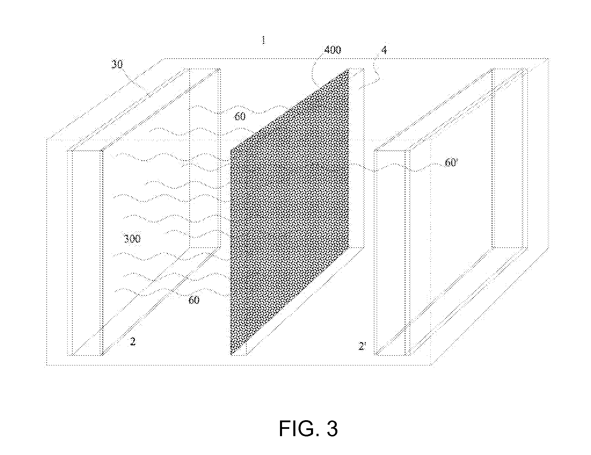
flat panel X-ray source(s) which generate a wide source of X-ray flux, disposed inside a radiation shielding enclosure, with a
material transport system provided to move the material to be irradiated from outside the enclosure to an irradiation section inside the enclosure. Shielded sections of the enclosure before and after the irradiation section protect surrounding people from any
stray radiation. The one or more flat panel X-ray sources are disposed in the irradiation section so as to have their flux emitting surfaces facing inwards towards the material being transported through that section. With flat panel X-ray sources on either side of the material, most X-ray flux which passes by or through the material being irradiated will be absorbed by the anode of the opposite flat panel X-ray source, providing a degree of self-shielding. This and the much lower energies generated from the X-ray sources (mean energies generally under 100 kV) very substantially reduce the need for additional shielding materials as compared with prior art panoramic irradiators, one factor allowing the irradiator of this disclosure to be made in a relatively compact format. Since the X-ray sources are wide, and the flux generation area is substantially equal to the irradiation target area, minimal throw distance is needed compared with a
point source, another factor allowing the irradiator to be made more compact. The irradiator of this disclosure can be made small enough to fit in the shipping bay of a product manufacturing site, to be installed in-line with a manufacturing process, or be loaded onto or assembled into a trailer. It can also be made modular, with sections of the irradiator section joined together for additional irradiation process capacity. Many types of
material transport mechanisms can be used. A
conveyor belt can transport solids, including packaged products. Pipes can transport fluids. Sheets of material can be transported through on rollers. The
material transport mechanism provides uniform flux delivery in one dimension. The flat panel X-ray sources can be designed to provide uniformity in the second dimension. The configuration of the material being irradiated and the use of X-ray sources on multiple sides of the irradiation chamber can provide a more uniform flux
dose map in the third dimension.
[0026]According to one embodiment of the present disclosure an apparatus and method for the X-
ray irradiation of materials. This apparatus includes an irradiation chamber, a number of flat electromagnetic (X-ray) sources, a transport and support mechanism, a
heat transfer system, and a shielding system. The
transport system allows materials to be transported to and from an interior volume of the irradiation chamber. End covers provide shielding such that essentially all the electromagnetic flux remains within the irradiation system without irradiating the exterior environment. A shielded portal within the shielding system allows access to an interior volume of the irradiation chamber. The shielded portal allows materials to be placed in and withdrawn from the irradiation chamber. When closed, the shielded portal allows a continuous shielded boundary of the interior volume of the irradiation chamber. The electromagnetic sources are positioned on or embedded with interior surfaces of the irradiation chamber. These electromagnetic sources may generate an electromagnetic flux, such as an X-ray flux, where this flux is used to irradiate the interior volume of the irradiation chamber and any materials placed therein. The materials placed within the interior of the chamber may be supported by a low attenuation support mechanism. This low attenuation support mechanism does not substantially reduce the X-ray flux intended to irradiate the materials placed within the interior volume of the irradiation chamber. Additionally the irradiation chamber may have a
heat transfer system thermally coupled to the irradiation chamber and electromagnetic sources in order to remove heat from the interior surfaces of the irradiation chamber. The shielding system and end covers external to the irradiation chamber prevents unwanted radiation from escaping from within the irradiation chamber.
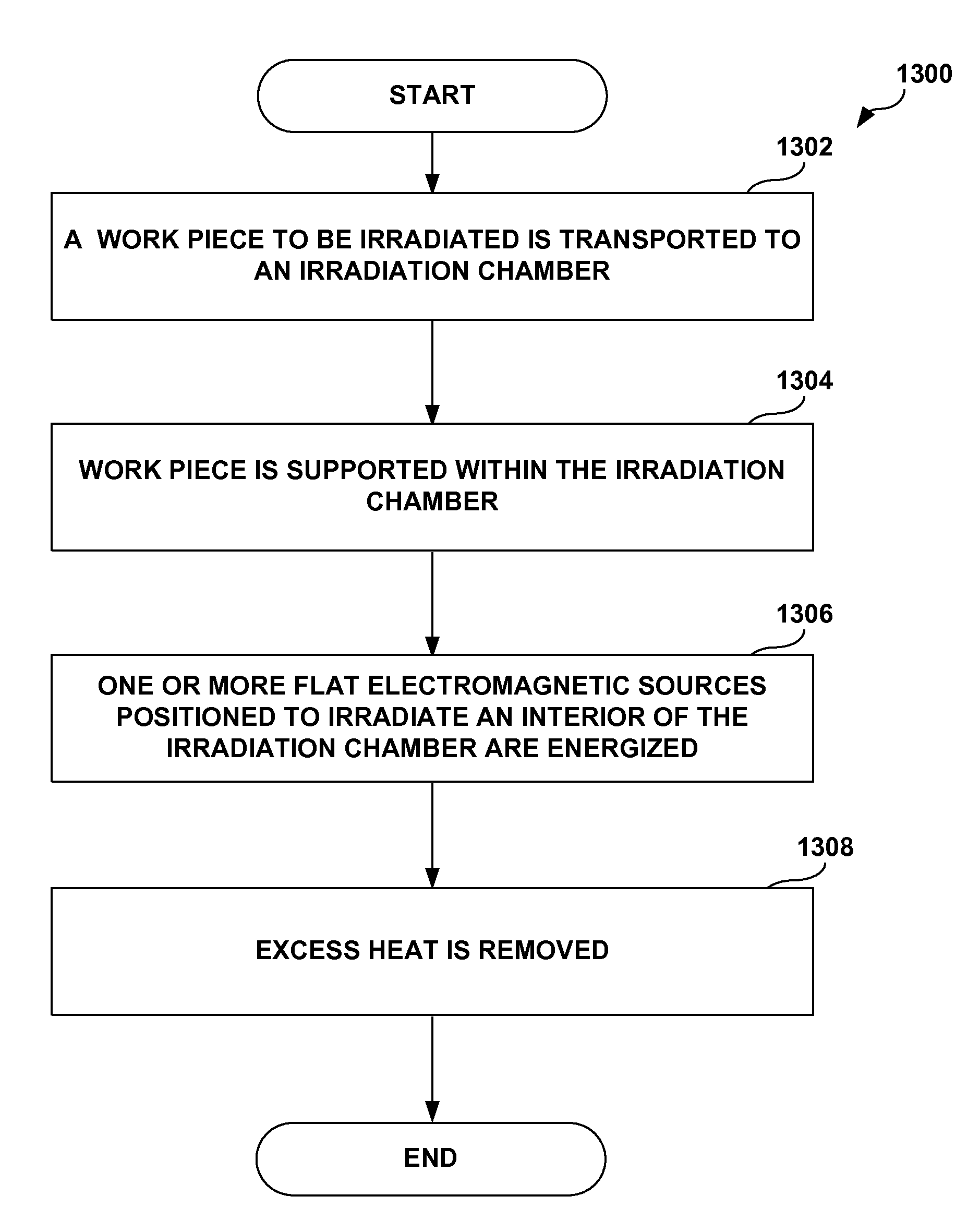
[0027]Another embodiment of the present disclosure provides a method for the X-ray irradiation of materials. This method involves transporting a work piece or material to be irradiated to and from an irradiation chamber. The work piece or materials are placed within the irradiation chamber and supported with a mechanism such as a low attenuation support mechanism. This low attenuation support mechanism does not substantially reduce the electromagnetic flux (X-ray) flux within the irradiation chamber. One or more flat electromagnetic (X-ray) sources may be energized to irradiate the interior volume of the irradiation chamber. This allows the work piece or materials to be irradiated within the chamber.
Excess heat may be removed with a
heat transfer system in order to prevent the irradiation chamber / electromagnetic source from overheating. Additionally the irradiation chamber may be shielded to prevent the irradiation of objects and materials external to the irradiation chamber.
[0028]Yet another embodiment of the present disclosure provides another system for the X-ray irradiation of materials. This system includes an irradiation chamber, a number of flat X-ray sources, a transport mechanism, a low attenuation support mechanism, a heat
transfer system, a shielding system, and a process controller. The irradiation chamber has an inner volume wherein the flat X-ray sources are positioned within or on the interior surfaces of the irradiation chamber such that the flat X-ray sources may irradiate the interior volume of the irradiation chamber. The transport mechanism allows materials to travel to and from the irradiation chamber. Within the irradiation chamber the low attenuation support mechanism supports the work pieces or materials to be irradiated while not substantially reducing the X-ray flux available for the irradiation of these objects. The heat
transfer system removes heat from the X-ray source and the shielding system external to the irradiation chamber prevents inadvertent irradiation of materials and objects outside the irradiation chamber. The process controller coordinates the operation of the irradiation chamber, X-ray source, heat
transfer system and an
interlock system which prevents irradiation while access to the interior volume is open.

