

Lithium ion rechargeable battery and process for producing the lithium ion rechargeable battery
a lithium ion rechargeable battery, multi-layer technology, applied in sustainable manufacturing/processing, non-aqueous electrolyte cells, cell components, etc., can solve the problems of not always forming useful reaction products, affecting the overall electric characteristics and mechanical characteristics of batteries, and reducing the interface resistance. , the effect of reducing the internal resistance of the battery
- Summary
- Abstract
- Description
- Claims
- Application Information
AI Technical Summary
Benefits of technology
Problems solved by technology
Method used
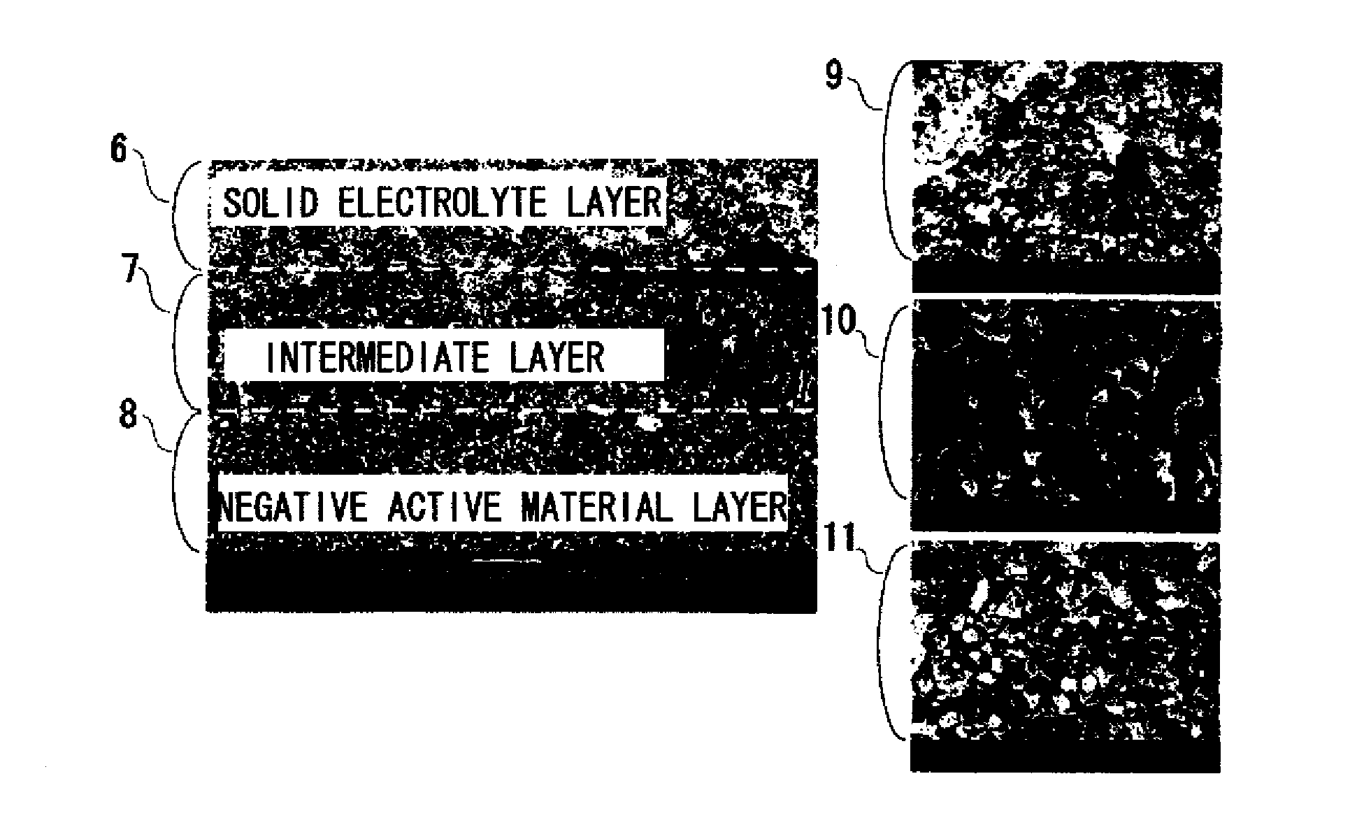
Image

Examples
example 1
[0170]Hereinafter, examples are used to describe the present invention in detail. In addition, the expression “parts” means parts by weight, unless otherwise specified.
[0171](Preparation of a Positive Electrode Paste)
[0172]For the positive active material, LiMn2O4 prepared by a method described below was used.
[0173]Li2CO3 and MnCO3 were used as starting materials, and weighted to be at a mol ratio 1:4, water was used as a solvent to conduct wet blending in a ball mill for 16 hours, and then the mixture was dewatered and dried. The resulting powder was calcined in the air for two hours at a temperature of 800° C. The calcined product was roughly crushed, water was used as a solvent to conduct wet blending in a ball mill for 16 hours, and then the mixture was dewatered and dried to obtain a positive active material powder. The BET value of this powder was 13.4 m2 / g. An X-ray diffraction device was used to confirm that the composition of the prepared powder was LiMn2O4.
[0174]For a posi...
example 2
[0193]XRD analysis was used to study reactions between the solid electrolyte, the positive active material, and the negative active material by baking and to identify the reaction product.
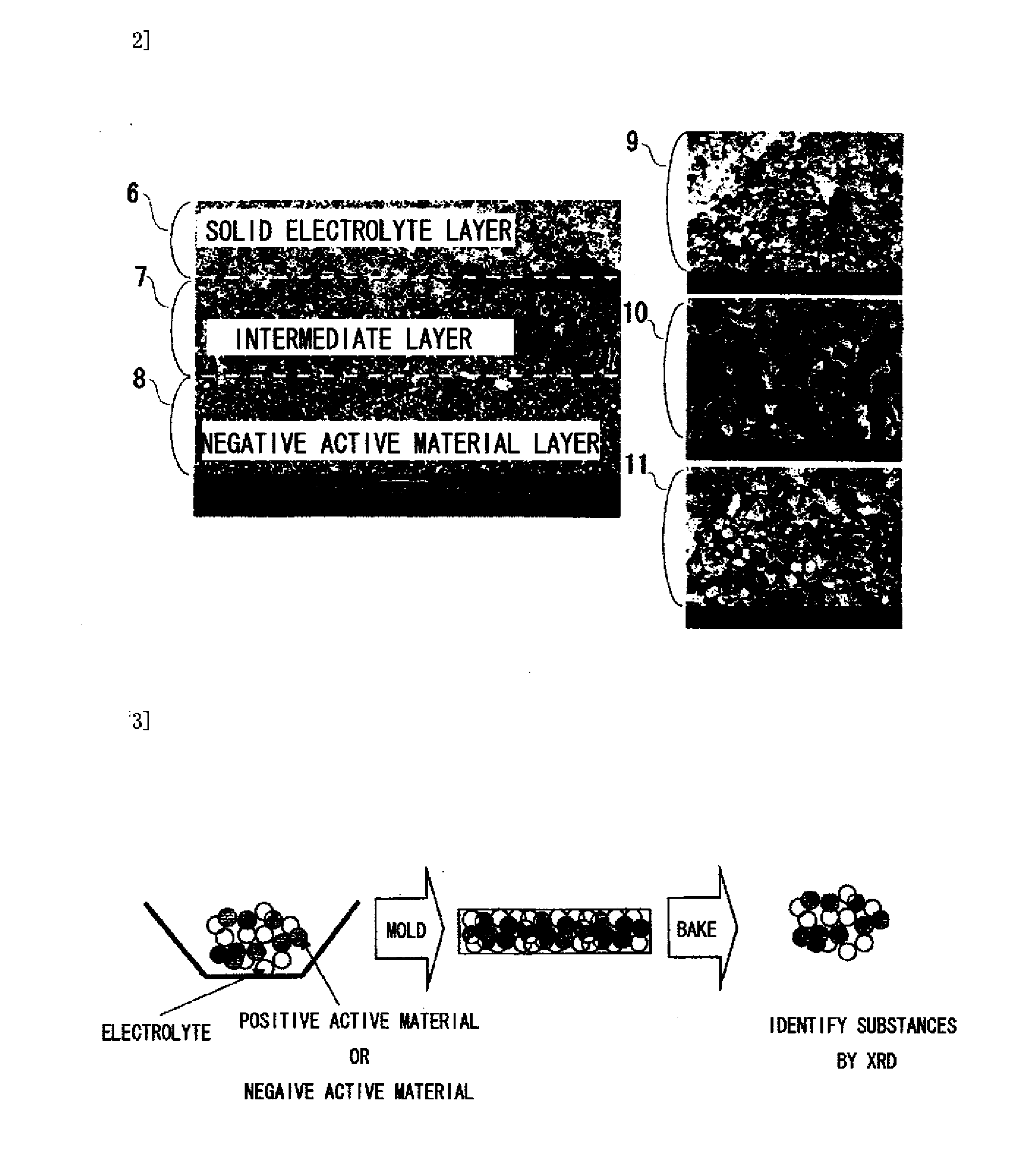
[0194]FIG. 3 is a work flowchart depicting a study experiment to study reactions between the solid electrolyte material and the active material.
[0195]A study method was conducted according to the process steps shown below.
(1) The solid electrolyte, the positive active material, and the negative active material were mixed in a mortar.
(2) The mixed powders were shaped in a mold to prepare a disk.
(3) The temperature of the prepared disk was increased to a set temperature at the rate of temperature rise of 200° C. / hr, kept for two hours, and then allowed to stand to cool. The set temperature was temperatures of 500, 600, 700, 800, 900, 960, 1000, and 1050° C.
(4) The baked disk was crushed in a mortar to form a sample.
(5) Substances were identified by XRD.
[0196]FIG. 4 shows XRD patterns of samples that ...
example 3
[0198]XRD analysis was conducted by a method similar to that of Example 2, reactions between the solid electrolyte and the active material by baking were studied, and reaction products were identified.
[0199]FIG. 10 shows XRD patterns of samples that a solid electrolyte Li3.5Si0.5P0.5O4 and an active material LiMn1.5Co0.5O4 were mixed and then baked. It is seen that in the pattern before baked and the pattern of baking at a temperature of 600° C., only the peaks of the solid electrolyte Li3.5Si0.5P0.5O4 and the active material LiMn4.5Co0.5O4 are observed, whereas in the patterns of baking at temperatures of 700° C. or greater, the peak of LiMnCoO4, which is a reaction product, is observed. LiMnCoO4 is a substance that functions as the active material.
[0200]FIG. 11 shows XRD patterns of samples that a solid electrolyte Li3.5Si0.5P0.5O4 and an active material LiMn1.5Ni0.5O4 were mixed and then baked. It is seen that in the pattern before baked and the patterns of baking at temperatures...
PUM
| Property | Measurement | Unit |
|---|---|---|
| thickness | aaaaa | aaaaa |
| temperatures | aaaaa | aaaaa |
| temperatures | aaaaa | aaaaa |
Abstract
Description
Claims
Application Information