Catalyst, process for preparing the same, and uses of the catalyst

Inactive Publication Date: 2010-09-09
SHOWA DENKO KK
View PDF8 Cites 26 Cited by
  • Summary
  • Abstract
  • Description
  • Claims
  • Application Information

AI Technical Summary

Benefits of technology

[0054]The catalyst of the present invention is not corroded in an acidic electrolyte or at a high potential, is stable, has high oxygen reduction abilit

Problems solved by technology

However, since platinum is high in price and is limited on the resource quantity, development of catalysts capable of substitution has been desired.
Further, precious metals used for the cathode surface sometimes dissolve in an acidic atmosphere, and there is a problem that they are not suitable for uses requiring durability over a long term.
In the materials containing these nonmetals, however, there is a problem that practically sufficient oxygen reduction ability as a catalyst has not been obtained.
The

Method used


Image

  • Catalyst, process for preparing the same, and uses of the catalyst
  • Catalyst, process for preparing the same, and uses of the catalyst
  • Catalyst, process for preparing the same, and uses of the catalyst

Examples


example 1

1. Preparation of Catalyst

[0196]600 mg (50 mmol) of carbon (available from Cabot Corporation, Vulcan 72) was sufficiently pulverized and mixed with 2.50 g (20 mmol) of niobium(IV) oxide (NbO2). In a tube furnace, the mixed powder was heated at 1600° C. for 1 hour in a nitrogen atmosphere, whereby 1.89 g of niobium carbonitride was obtained.

[0197]An X-ray powder diffraction spectrum of the resulting niobium carbonitride is shown in FIG. 1. The results of elemental analysis of the resulting niobium carbonitride are set forth in Table 1.

[0198]In a tube furnace, 1.02 g of the resulting niobium carbonitride was heated at 800° C. for 1 hour with flowing argon gas containing oxygen gas of 1% by volume, whereby 1.10 g of a niobium oxycarbonitride (also referred to as a “catalyst (1)” hereinafter) was obtained.

[0199]An X-ray powder diffraction spectrum of the catalyst (1) is shown in FIG. 10. Between diffraction angles 2θ of 33° and 43°, 4 diffraction peaks were observed. The results of elem...

example 2

1. Preparation of Catalyst

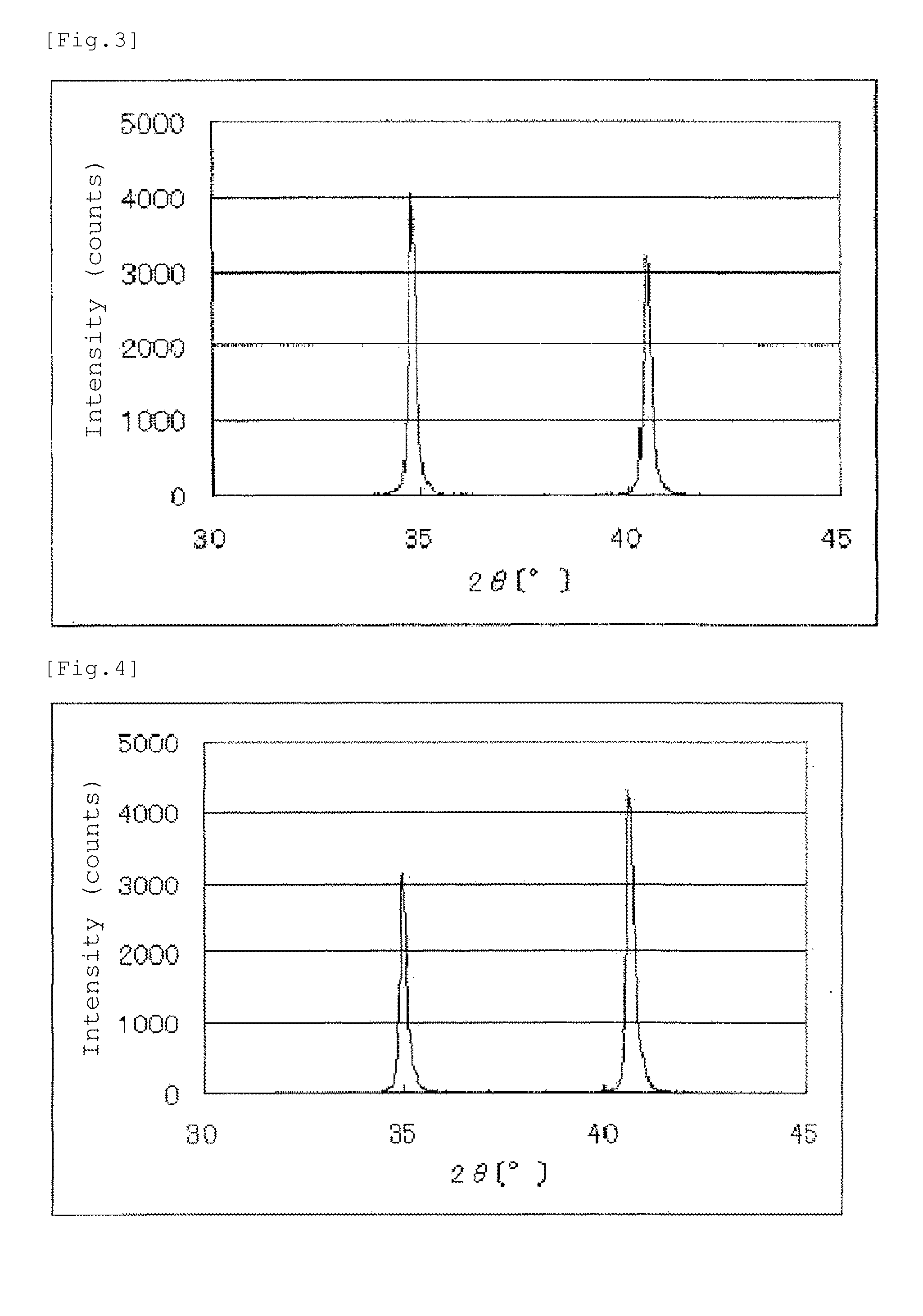
[0208]1.83 g of niobium carbonitride was prepared and from 1.02 g of the niobium carbonitride 1.09 g of a niobium oxycarbonitride (also referred to as a “catalyst (2)” hereinafter) was prepared in the same manner as in Example 1, except that the amount of carbon was changed to 480 mg (40 mmol) from 600 mg.

[0209]An X-ray powder diffraction spectrum of the resulting niobium carbonitride is shown in FIG. 2. The results of elemental analysis of the resulting niobium carbonitride are set forth in Table 1.

[0210]An X-ray powder diffraction spectrum of the catalyst (2) is shown in FIG. 11. Between diffraction angles 2θ of 33° and 43°, 4 diffraction peaks were observed. The results of elemental analysis of the catalyst (2) are set forth in Table 2. The BET specific surface area of the catalyst (2) was 2.3 m2 / g.

2. Preparation of Electrode for Fuel Cell

[0211]An electrode (2) for a fuel cell was obtained in the same manner as in Example 1, except that the catalyst (2) ...

example 3

1. Preparation of Catalyst

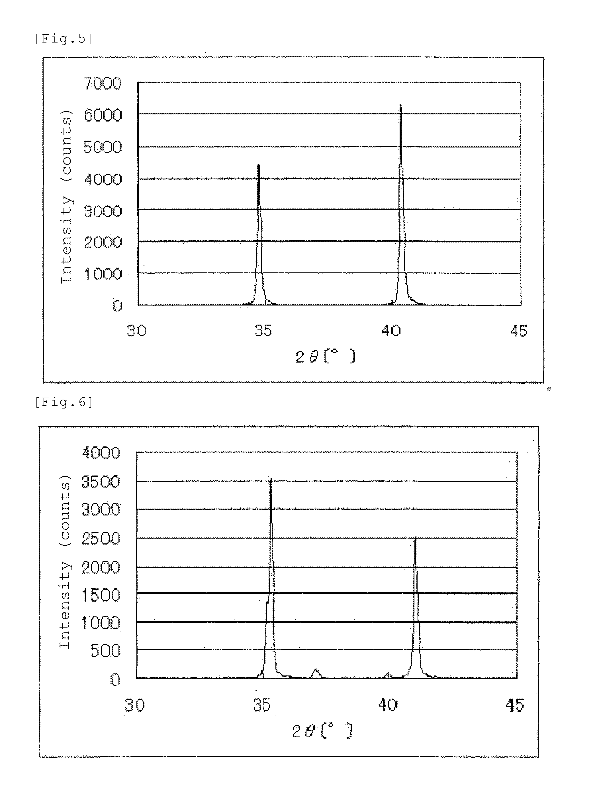
[0214]2.19 g of niobium carbonitride was prepared and from 1.02 g of the niobium carbonitride 1.09 g of a niobium oxycarbonitride (also referred to as a “catalyst (3)” hereinafter) was prepared in the same manner as in Example 1, except that the amount of carbon was changed to 720 mg (60 mmol) from 600 mg.

[0215]An X-ray powder diffraction spectrum of the resulting niobium carbonitride is shown in FIG. 3. The results of elemental analysis of the resulting niobium carbonitride are set forth in Table 1.

[0216]An X-ray powder diffraction spectrum of the catalyst (3) is shown in FIG. 12. Between diffraction angles 2θ of 33° and 43°, 4 diffraction peaks were observed. The results of elemental analysis of the catalyst (3) are set forth in Table 2. The BET specific surface area of the catalyst (3) was 2.1 m2 / g.

2. Preparation of Electrode for Fuel Cell

[0217]An electrode (3) for a fuel cell was obtained in the same manner as in Example 1, except that the catalyst (3) ...


PUM

PropertyMeasurementUnit
Temperatureaaaaaaaaaa
Angleaaaaaaaaaa
Angleaaaaaaaaaa

Abstract

The present invention provides a catalyst which is not corroded in an acidic electrolyte or at a high potential, is excellent in durability and has high oxygen reduction ability. The catalyst of the present invention is characterized by including a niobium oxycarbonitride. The catalyst of the invention is also characterized by including a niobium oxycarbonitride represented by the composition formula NbCxNyOz, wherein x, y and z represent a ratio of the numbers of atoms and are numbers satisfying the conditions of 0.01≦x≦2, 0.01≦y≦2, 0.01≦z≦3 and x+y+z≦5.

Description

TECHNICAL FIELD[0001]The present invention relates to a catalyst, a process for preparing the same, and uses of the catalyst.BACKGROUND ART[0002]Fuel cells are classified into various types according to the type of electrolyte and the type of electrode, and as typical fuel cells, there are fuel cells of alkali type, phosphoric acid type, molten carbonate type, solid electrolyte type and solid polymer type. Of these, the solid polymer type fuel cells capable of working at a temperature of a low temperature (about −40° C.) to about 120° C. have been paid attention, and in recent years, development and practical use of them as low pollution power sources for automobiles have been promoted. As uses of the solid polymer type fuel cells, vehicle driving sources or stationary electric sources have been studied, but in order to apply the fuel cells to these uses, durability over a long term is desired.[0003]This polymer solid type fuel cell is a fuel cell of such a type that a polymer solid...

Claims


Application Information

Patent Timeline
IPC IPC(8): H01M8/10H01M4/90B01J27/20
CPCB01J27/24H01M4/8828H01M4/9016Y02E60/50H01M2008/1095H01M4/90H01M4/96
Inventor MONDEN, RYUJIKONUMA, HIROSHISHISHIKURA, TOSHIKAZUKUROZUMI, TADATOSHI
Owner SHOWA DENKO KK
Why Eureka
Try Eureka