Photoelectric conversion module
a conversion module and photoelectric technology, applied in the direction of photometry using electric radiation detectors, optical radiation measurement, instruments, etc., can solve the problem of deteriorating high frequency characteristics
- Summary
- Abstract
- Description
- Claims
- Application Information
AI Technical Summary
Benefits of technology
Problems solved by technology
Method used
Image

Examples
embodiment 1
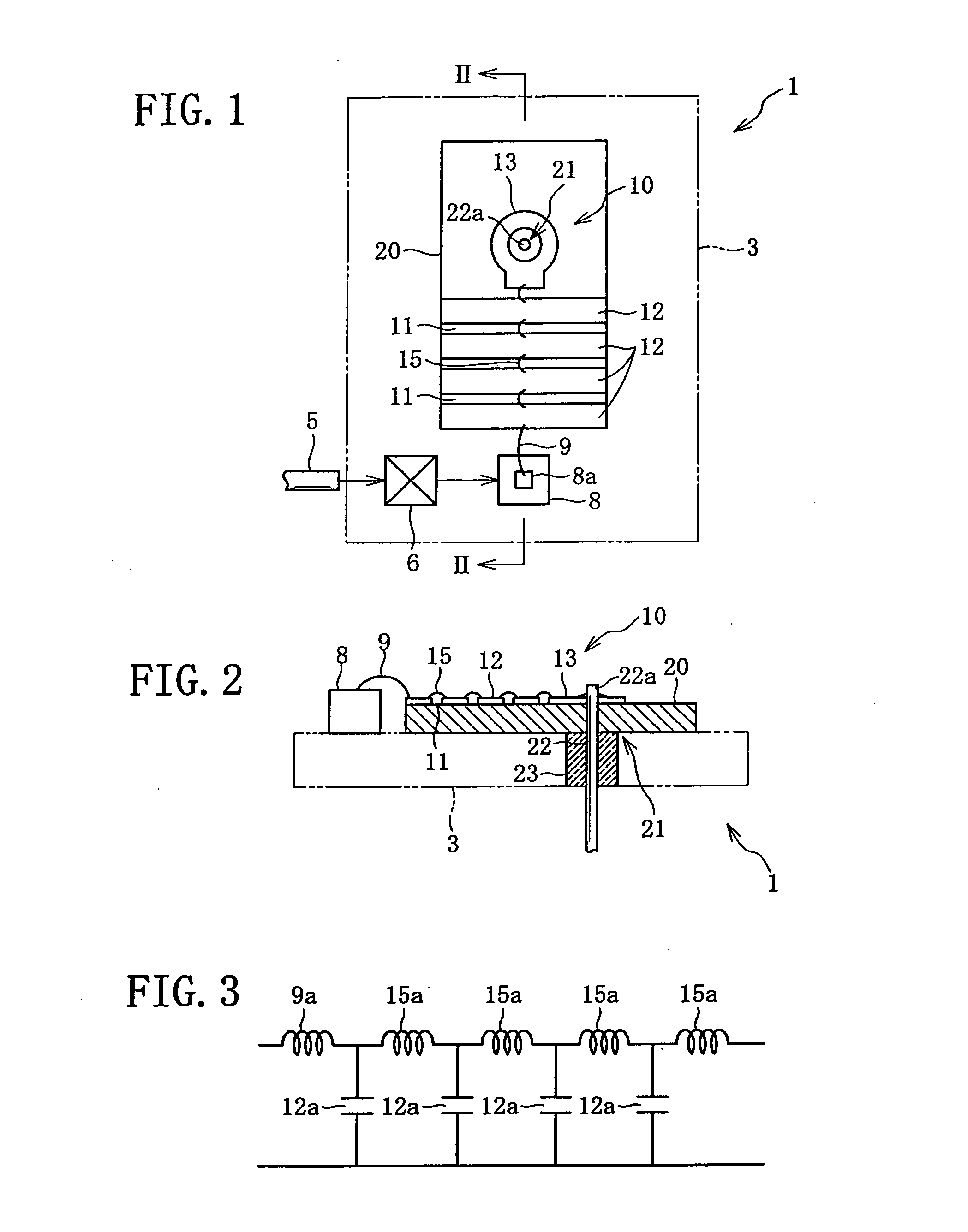
[0072]In the following, this photoelectric conversion module 1 will be explained with reference to the drawings.
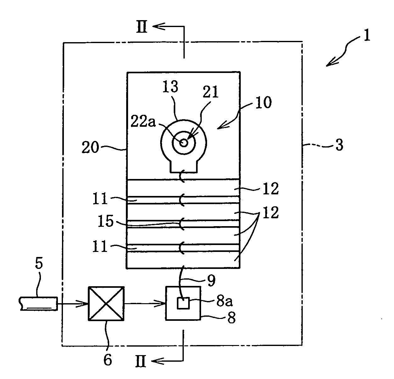
[0073]As shown in FIGS. 1 and 2, this photoelectric conversion module 1 is a module which converts an optical signal that has arrived by broadband transmission via an optical fiber 5 into an electrical signal and outputs that electrical signal. This photoelectric conversion module 1 comprises a package 3, an optical lens 6 (i.e., an optical window), a photoelectric conversion element 8 that performs photoelectric conversion upon an optical signal, an impedance matching circuit 10 that is provided between an output electrode 8a of the photoelectric conversion element 8 and a signal output circuit 21, a substrate 20 upon which the impedance matching circuit 10 is installed, and the signal output circuit 21 that outputs the signal converted by the photoelectric conversion to the exterior, etc.
[0074]The photoelectric conversion element 8 is a typical photo-diode element, and i...
embodiment 2
[0094]Next, a photoelectric conversion module 1A according to a second embodiment will be explained.
[0095]To elements of this photoelectric conversion module 1A as shown in FIGS. 7 and 8 which are similar in structure to elements of the first embodiment, the same reference symbols are appended, and explanation thereof is omitted. With this photoelectric conversion module 1A, a single amplifier 30 and two impedance matching circuits 10 are provided between the photoelectric conversion element 8 and two signal output sections 21.
[0096]The amplifier 30 is connected to the output electrode 8a of the photoelectric conversion element 8, and amplifies the photoelectrically converted electrical signal. This amplifier 30 can amplify the single phase electrical signal that has been converted by the photoelectric conversion element 8 and convert this single phase signal into two differential signals, which it then can output from the two signal output sections 21 to the exterior of the photoel...
embodiment 3
[0098]Next, an impedance matching circuit 10B of a photoelectric conversion module 1B according to a third embodiment will be explained. To elements of this photoelectric conversion module 1B as shown in FIGS. 9 and 10 which are similar in structure to elements of the first embodiment, the same reference symbols are appended, and explanation thereof is omitted.
[0099]This impedance matching circuit 10B comprises a plurality of metallic coating layers 12 and a plurality of metallic wires 15 (these are equivalent to metallic connecting lines), and is provided between a signal input unit 35 that corresponds to the photoelectric conversion element 8 of the first embodiment or to the amplifier 30 of the second embodiment, and a signal output section 21B. This impedance matching circuit 10B is mounted upon a substrate 20B. The plurality of metallic coating layers 12 and the plurality of metallic wires 15 are the same as in the first embodiment.
[0100]The metallic coating layer 12 at the inp...
PUM
 Abstract
Description
Claims
Application Information
PatSnap Eureka turns technology decisions into work you can execute. Powered by our Innovation Knowledge Graph, it runs expert workflows across engineering, life sciences, materials and intellectual property. Get your review-ready output in minutes.


