

Method of manufacturing permanent magnet and permanent magnet
a manufacturing method and permanent magnet technology, applied in the field of permanent magnet manufacturing, can solve the problems of deterioration through machining, affecting the effect of machining, so as to achieve the effect of improving or recovering
- Summary
- Abstract
- Description
- Claims
- Application Information
AI Technical Summary
Benefits of technology
Problems solved by technology
Method used
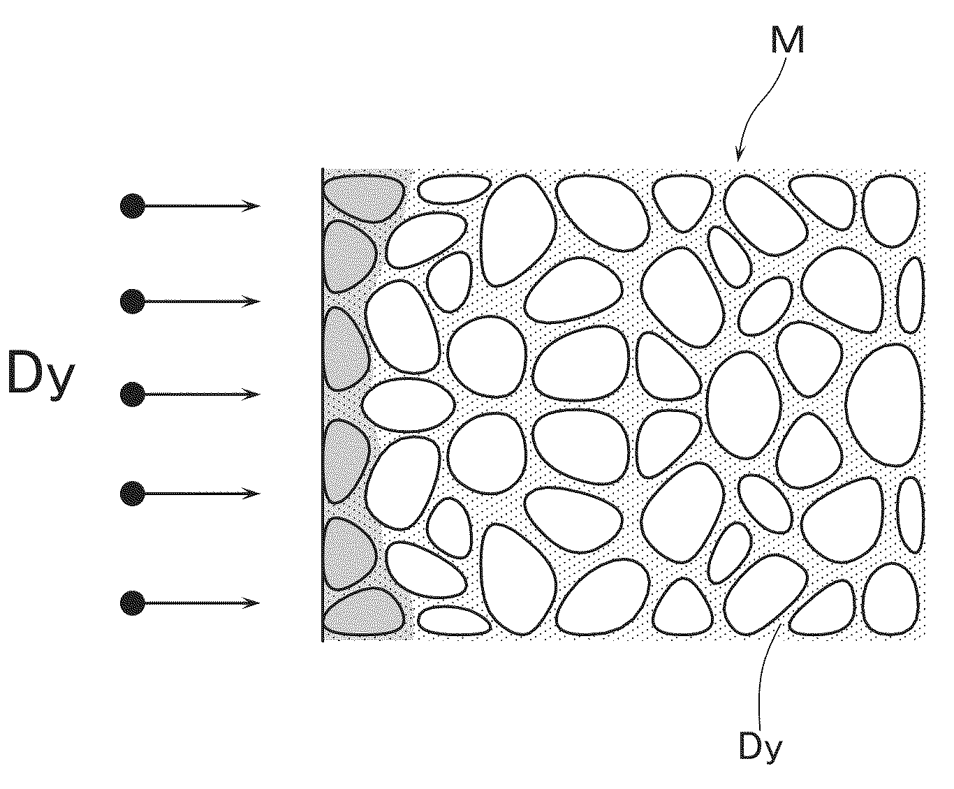
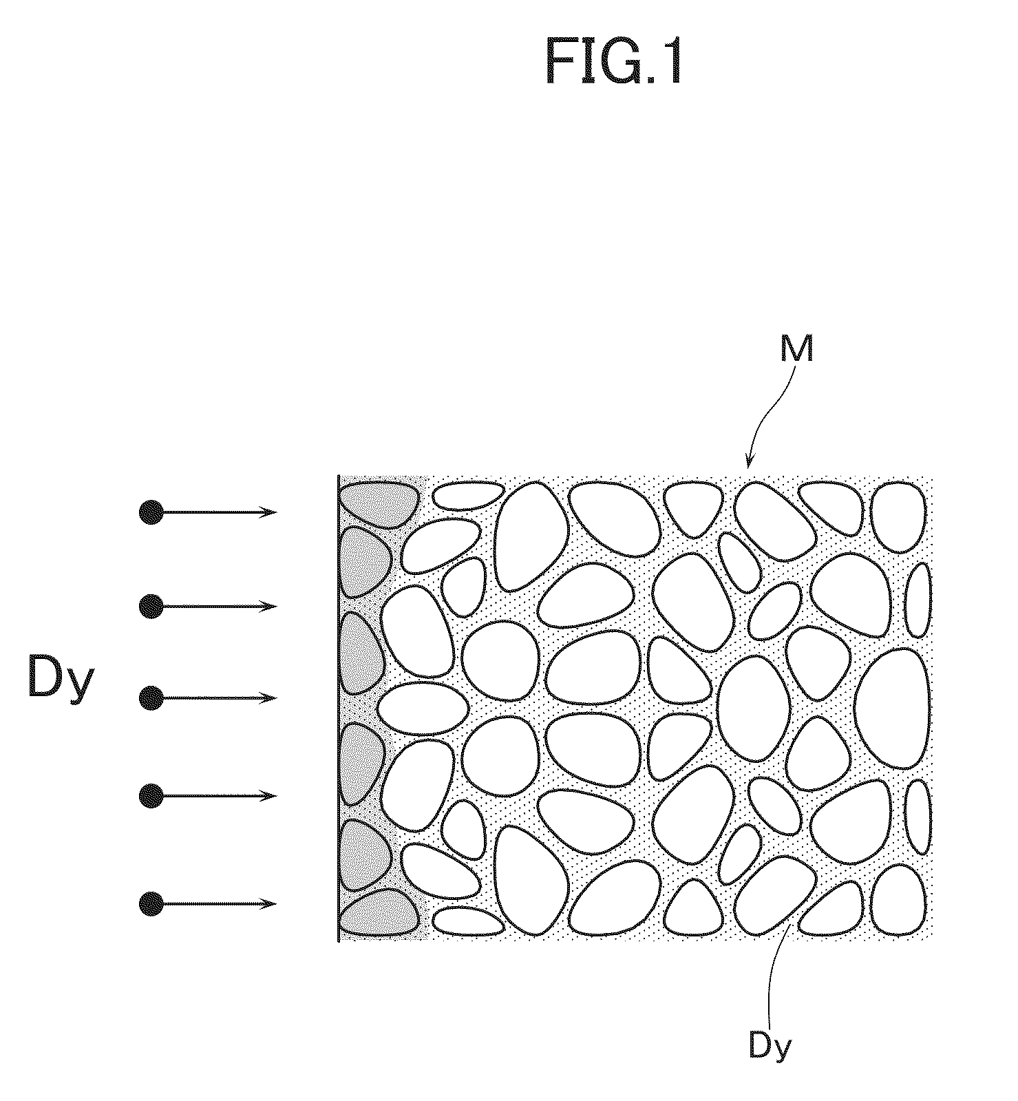
Image

Examples
example 1
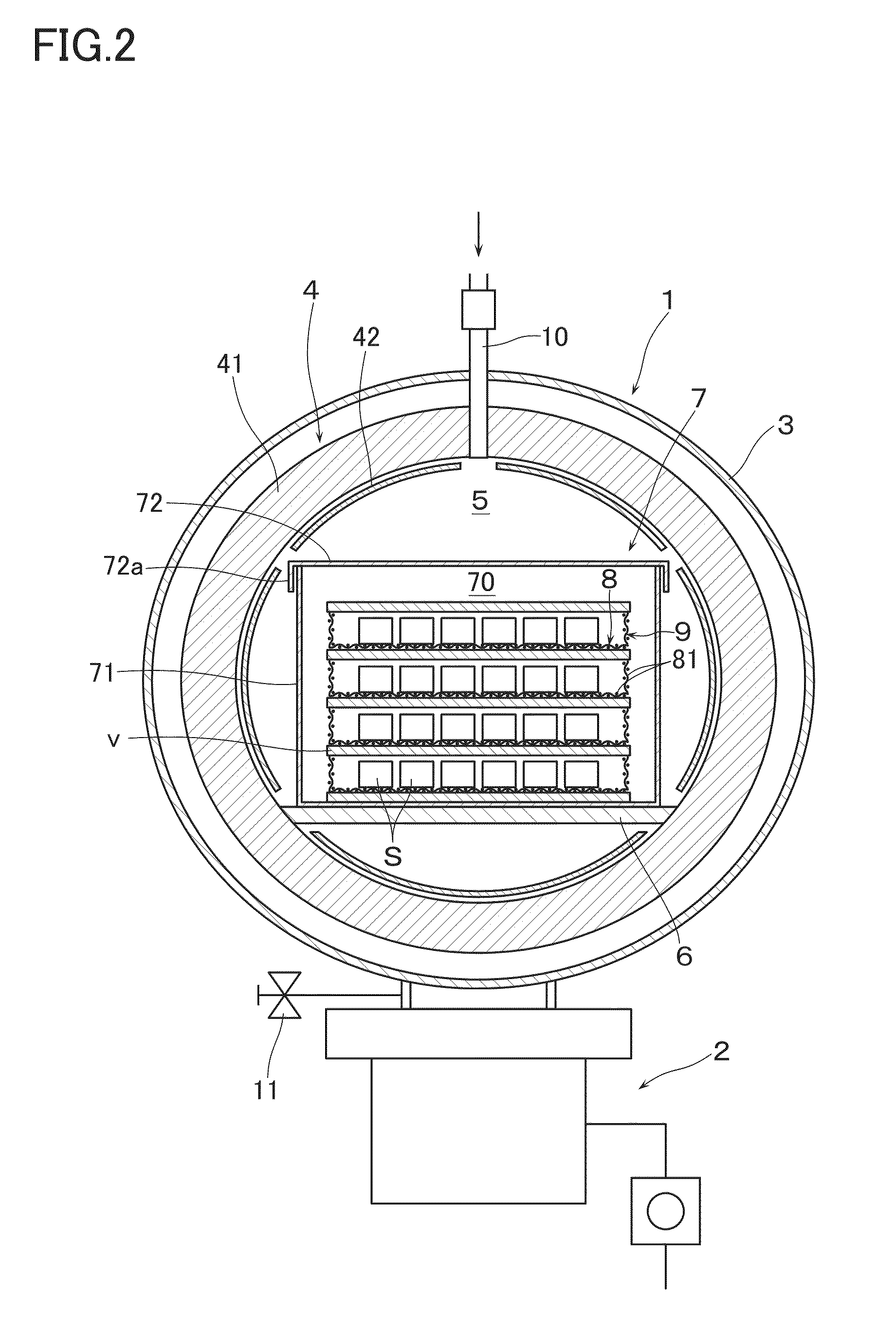
[0067]In Example 1, by using the vacuum vapor processing apparatus 1 as shown in FIG. 2, the following sintered magnets S were subjected to vacuum vapor processing to thereby obtain permanent magnets M. As the sintered magnets S, with industrial pure iron, metallic neodymium, low-carbon ferroboron, electrolysis cobalt, and pure copper as raw materials, the mixing composition (weight %) was arranged to be 25Nd-7Pr-1B-0.05Cu-0.05Ga-0.05Zr-Bal Fe (Sample 1), 7Nd-25Pr-1B-0.03Cu-0.3Al-0.1Nb-Bal Fe (Sample 2), 28Nd-1B-0.05Cu-0.01Ga-0.02Zr-Bal Fe (Sample 3), 27Nd-2Dy-1B-0.05Cu-0.05Al-0.05Nb-Bal Fe (Sample 4), 29Nd-0.95B-0.01Cu-0.02V, 0.02Zr-Bal Fe (Sample 5), 32Nd-1.1B-0.03Cu-0.02V-0.02Nb-Bal Fe (Sample 6), and 32Nd-1.1B-0.03Cu-0.02V-0.02Nb-Bal Fe (Sample 7). These samples were subjected to vacuum induction melting, and thin-piece ingots of about 0.3 mm thick were obtained by strip casting method. Then, they were once coarsely ground by hydrogen grinding process and subsequently finely gro...
example 2
[0072]In Example 2, by using the vacuum vapor processing apparatus 1 as shown in FIG. 2, the sintered magnets S that were manufactured in the same manner as the sample 6 in Example 1 were subjected to vacuum vapor processing. There were, however, prepared samples of the thicknesses of the sintered magnets respectively of 1, 3, 5, 10, 15 and 20 mm. On the spacers ten sintered magnets and Dy (99.5%) that was formed into a plate shape of 0.5 mm thick were stacked in the vertical direction, and were housed into the processing box 7 of W make. At this time, cylindrical bodies of Mo make were vertically disposed on four corners of the spacers so that the spacing between the metal evaporating materials v and the upper surface or the lower surface of the sintered magnets S could be adequately varied.
[0073]Next, as conditions at the time of vacuum vapor processing, after the pressure inside the vacuum chamber 3 has reached 10−5 Pa, the heating means 4 was operated, and the temperature inside...
example 3
[0077]In Example 3, by using the vacuum vapor processing apparatus 1 as shown in FIG. 2, vacuum vapor processing was carried out on sintered magnets S. As the sintered magnets, there were prepared ones available on the market having the composition of 28.5(Nd+Pr)-3Dy-0.5Co-0.02Cu-0.1Zr-0.05Ga-1.1B-Bal. Fe, and 20×20×t mm (thickness t was 1.5 mm and 10 mm).
[0078]Then, after having disposed ten sintered magnets on a spacer, another spacer was placed on top of the above-described spacer, and a total weight of 5 g of Dy (99.5%) in particle form was disposed, thereby housing them into the processing box 7 of W make.
[0079]Then, as the conditions for the vacuum vapor processing, after the pressure inside the vacuum chamber 3 has reached 10−4 Pa, the heating means 4 was operated, and the temperature inside the processing chamber 70 (vacuum vapor processing step) was set to 900° C. After Dy has started evaporation, Ar gas was appropriately introduced into the vacuum chamber 3. At a pressure ...
PUM
| Property | Measurement | Unit |
|---|---|---|
| pressure | aaaaa | aaaaa |
| partial pressure | aaaaa | aaaaa |
| time | aaaaa | aaaaa |
Abstract
Description
Claims
Application Information