
Active optical fiber and method for fabricating an active optical fiber

a technology of active optical fiber and active components, which is applied in the field of active optical fiber, optical fiber amplifier and optical fiber laser, can solve the problems of limiting the output power of an active component, affecting so as to achieve stable polarization state, increase the efficiency of active devices, and inherent spectral selectivity

Active Publication Date: 2010-09-30
AMPLICONYX OY
View PDF15 Cites 31 Cited by
  • Summary
  • Abstract
  • Description
  • Claims
  • Application Information

AI Technical Summary

Benefits of technology

[0017]In one embodiment of the method according to the present invention the diameter of the preform is decreased by pre-drawing the preform prior to drawing the fiber.
[0033]In light of the previous discussion the tapered section of active optical fiber according to the present invention has several features which all contribute to overcoming the issue of limited pumping efficiency and limited power scaling capability of prior-art active fibers and fiber devices. These issues are even more pronounced in active fibers and devices with single-mode output. The most important beneficial features of the present invention comprise the long optical path of a tapered section of fiber, the continuous mode conversion process, the big core / cladding diameter ratio, the large volume of the active core, the large acceptance aperture for pump-light power at the input and the inherent spectral selectivity. These features together dramatically increase the efficiency and power scaling capability of active optical fiber devices. One application for the present invention is for example an active optical device with single-mode output where the problems of limited pump-light efficiency and limited output power are more pronounced.

Problems solved by technology

Firstly, there is a limitation on the level of pump power that can be launched into a double clad fiber. This consequently limits the power scaling capability of fiber lasers and amplifiers. Furthermore in single mode fibers the fundamental mode propagation requirement imposes restrictions on the largest core diameter. This requirement dictates that even for fibers with a small numerical aperture (NA<0.07) a core diameter should not exceed 12 μm for an operational wavelength of 1 μm. At the same time, since pump absorption in a double clad fiber depends on the core / cladding diameter ratio, the outer diameter of a double clad fiber should not exceed 300-400 μm. Taking into account the limited brightness of available pump sources, the limitation in the fiber diameter automatically leads to a limitation in the output power of an active component.
Secondly, the pump absorption coefficient for each cladding propagated mode is determined by the overlap between the mode field distribution and the dopant (e.g. rare earth ions) distribution in the core. As a result, each mode will be absorbed with different efficiency due to a difference in the mode field distribution of various modes. So, virtually, it is possible to divide all cladding propagated modes into two groups—“absorbable” and “unabsorbable” modes.
Therefore the modes in this group are not absorbed efficiently in the core of the fiber and do not notably contribute to light amplification.
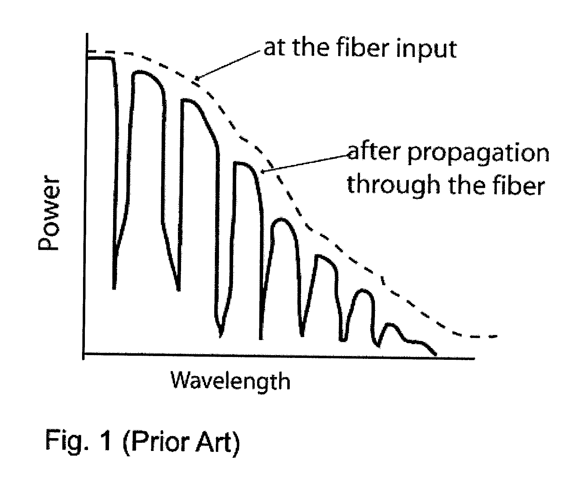
The non-uniform distribution of population inversion along the fiber length is largely a result of the change in modal content of the pump radiation with propagation distance.
This causes deterioration in the pump conversion efficiency of lasers and amplifiers.
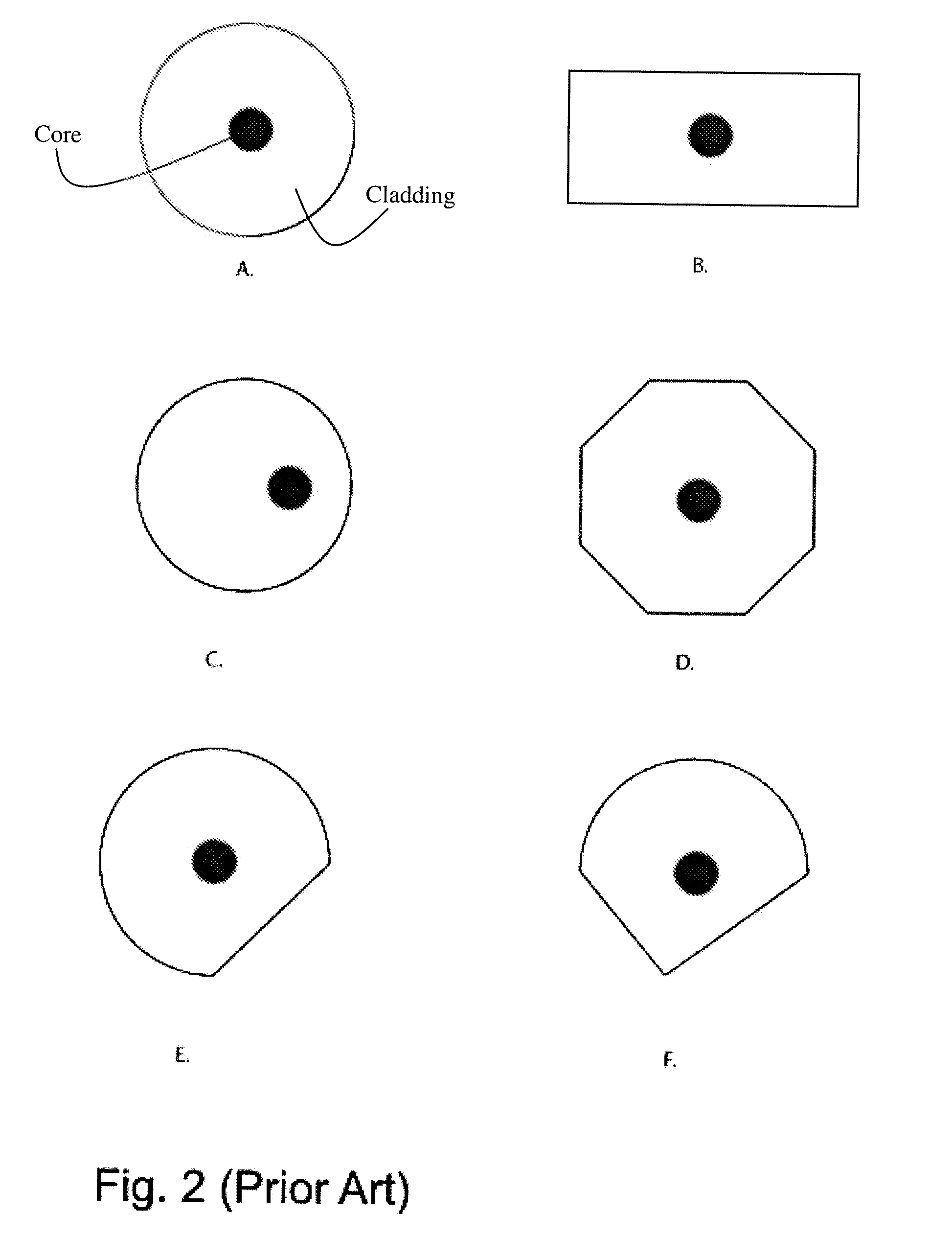
It is known from prior-art that a special geometry of the cladding leads to an increase in the pump power absorption, but by no means completely eliminates the problem of saturation of the absorption.
Furthermore this method is applicable only for relatively thin fibers with an outer diameter of cladding of less than 200 μm, because it is difficult to bend a 300-600 μm diameter fiber with the required spatial period.
Additionally, a chaotic mechanical stress and perturbation of cladding may lead to the coupling between skew and leakage rays resulting in an increase in the loss of pump power.
This would lead to deterioration in the efficiency of an active component.
This method has an obvious disadvantage as scattering at the “truncated regions” embedded directly into the cladding will inevitably lead to significant leakage of the pump power out of the fiber.
I.e. the method will result in pumping losses.

Method used


Image

  • Active optical fiber and method for fabricating an active optical fiber
  • Active optical fiber and method for fabricating an active optical fiber
  • Active optical fiber and method for fabricating an active optical fiber

Examples


Embodiment Construction

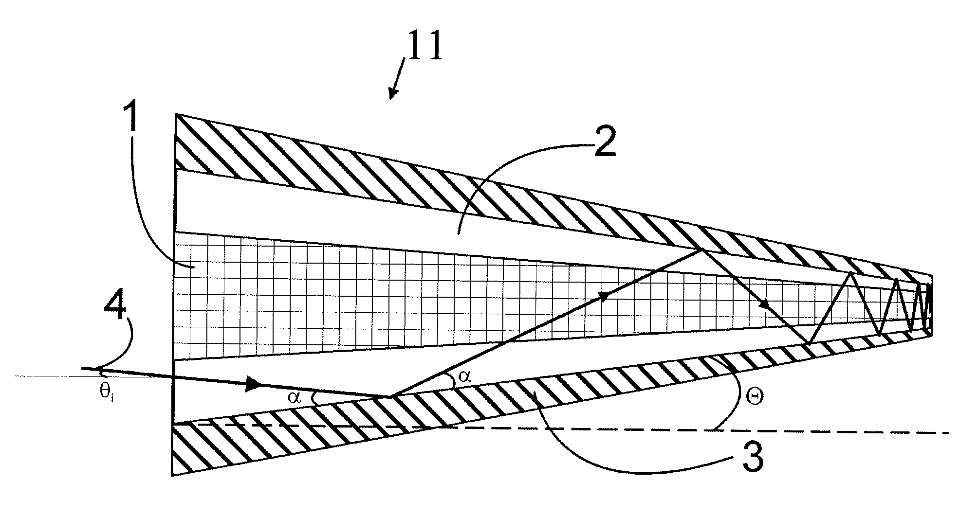
[0043]FIG. 4 shows a longitudinal cross section of a tapered section of a double clad active optical fiber 11 according to one embodiment of the present invention. The section of fiber comprises an active core 1, an inner cladding 2 and an outer cladding 3. The figure further shows the tapering profile 6 of the section of fiber. The tapering profile 6 of the outer cladding 3 of the fiber is presented in terms of the diameter of the section of fiber 11 as a function of the position on the section of fiber 11. In the example of FIG. 4 the tapering profile of all of the aforementioned three layers follows a linear function although other profiles may be utilized as well. Considering the method of manufacturing it is feasible to consider an example where all of the layers of the section of fiber have the same functional dependence for their longitudinal profile. Nevertheless according to the present invention only the core 1 and the inner cladding 2 in which the pump power propagates ne...


PUM

PropertyMeasurementUnit
Temperatureaaaaaaaaaa
Lengthaaaaaaaaaa
Thicknessaaaaaaaaaa

Abstract

A section of active optical fiber (11) which comprises an active core (1), an inner cladding layer (2) and an outer cladding layer (3). The diameter of said core 91) and the thickness of said inner cladding (2) change gradually along the length of said section of active optical fiber (11). This forms tapered longitudinal profile enabling a continuous mode conversion process along the length of the section of fiber (11). The method for fabricating a section of tapered active optical fiber comprises the steps of fabricating a perform for drawing active optical fiber from said perform, installing said perform into a drawing tower, drawing optical fiber in said drawing tower and altering at least one of the two parameters including the take-off perform speed and the take-up fiber speed during drawing of the optical fiber.

Description

FIELD OF THE INVENTION[0001]The present invention relates to active optical fibers, optical fiber amplifiers and optical fiber lasers.BACKGROUND OF THE INVENTION[0002]Double clad active optical fibers are widely used in fiber lasers and amplifiers. Fiber lasers and amplifiers with a CW output power of up to several kilowatts have been demonstrated. Besides to the obvious advantages the known double clad active optical fibers have serious shortcomings.[0003]Firstly, there is a limitation on the level of pump power that can be launched into a double clad fiber. This consequently limits the power scaling capability of fiber lasers and amplifiers. Furthermore in single mode fibers the fundamental mode propagation requirement imposes restrictions on the largest core diameter. This requirement dictates that even for fibers with a small numerical aperture (NA<0.07) a core diameter should not exceed 12 μm for an operational wavelength of 1 μm. At the same time, since pump absorption in a...

Claims


Application Information

Patent Timeline
IPC IPC(8): G02B6/036B23P17/00G02B6/26
CPCC03B37/02763Y10T29/49982C03B2203/04C03B2203/06C03B2203/18C03B2203/32C03B2205/40C03B2205/44G02B6/036G02B6/14H01S3/06708H01S3/06745H01S3/094007H01S3/094011C03B2203/02
Inventor FILIPPOV, VALERYCHAMOROVSKIY, YURIYOKHOTNIKOV, OLEGPESSA, MARKUS
Owner AMPLICONYX OY
Learn More