MEMS sensor, method of manufacturing MEMS sensor, and electronic apparatus

a manufacturing method and sensor technology, applied in the field of micro electro mechanical system sensor, can solve the problems that the inter-layer insulating layer between the two wiring layers the once formed inter-layer insulating layer cannot be used as a weight, etc., and achieves the effect of high accuracy and easy manufacturing

Active Publication Date: 2010-10-28
138 EAST LCD ADVANCEMENTS LTD
View PDF7 Cites 11 Cited by
  • Summary
  • Abstract
  • Description
  • Claims
  • Application Information

AI Technical Summary

Benefits of technology

[0008]An advantage of some aspects of the invention is to provide a MEMS sensor (for example, electrostatic capacitive acceleration sensor) in which the mass of a movable weight portion capable of moving in a direction perpendicular to a substrate can be efficiently increased, and a method o

Problems solved by technology

Since all inter-layer insulating layers are removed, the once formed inter-layer insulating layers cannot be used as

Method used


Image

  • MEMS sensor, method of manufacturing MEMS sensor, and electronic apparatus
  • MEMS sensor, method of manufacturing MEMS sensor, and electronic apparatus
  • MEMS sensor, method of manufacturing MEMS sensor, and electronic apparatus

Examples


first embodiment

1. First Embodiment

[0051]In a first embodiment, the invention is applied to an acceleration sensor module for a Z-direction that is a vertical direction of a substrate, and a sensor chip and an IC chip are integrally formed by a wafer process.

1.1. MEMS sensor

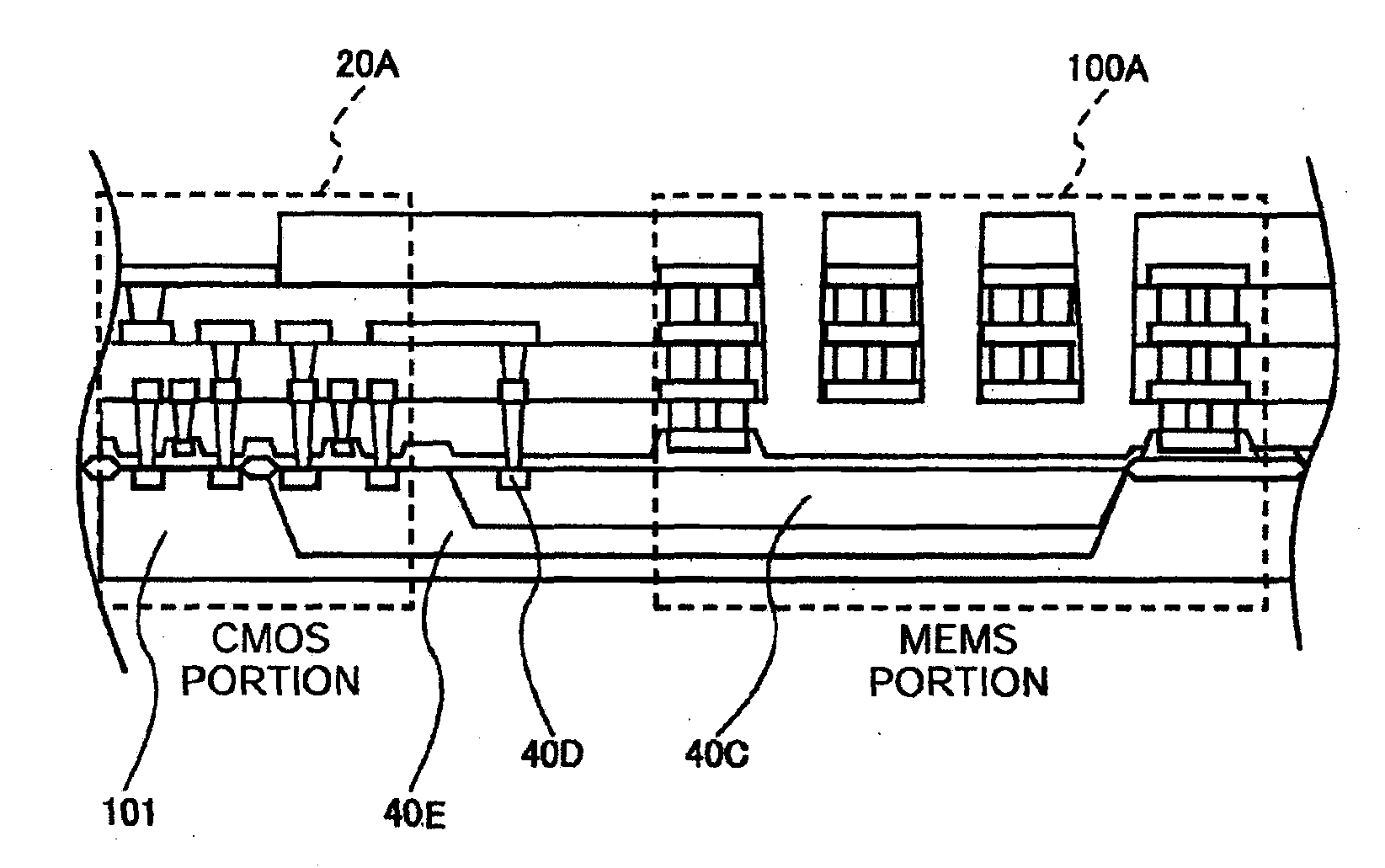
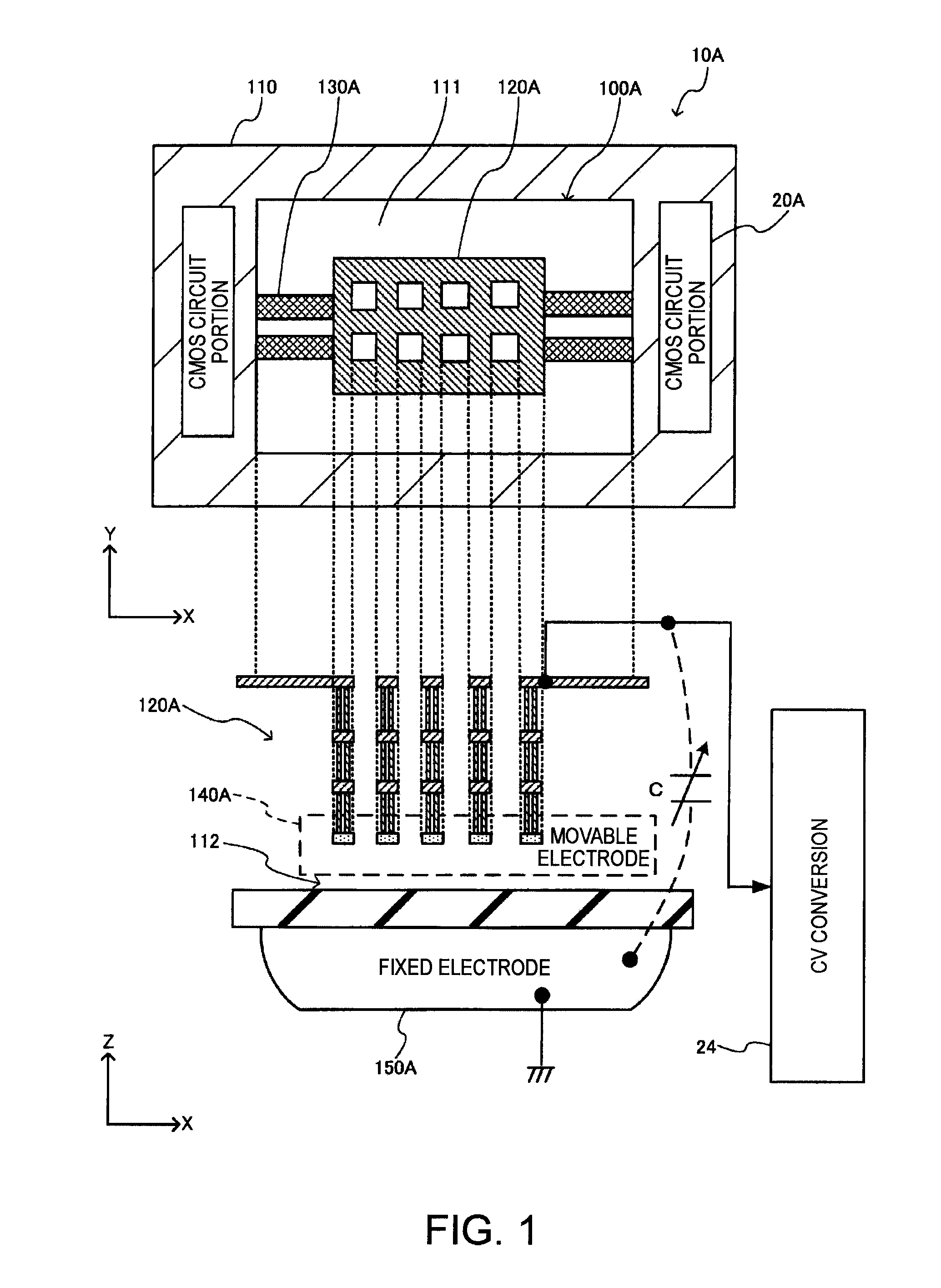
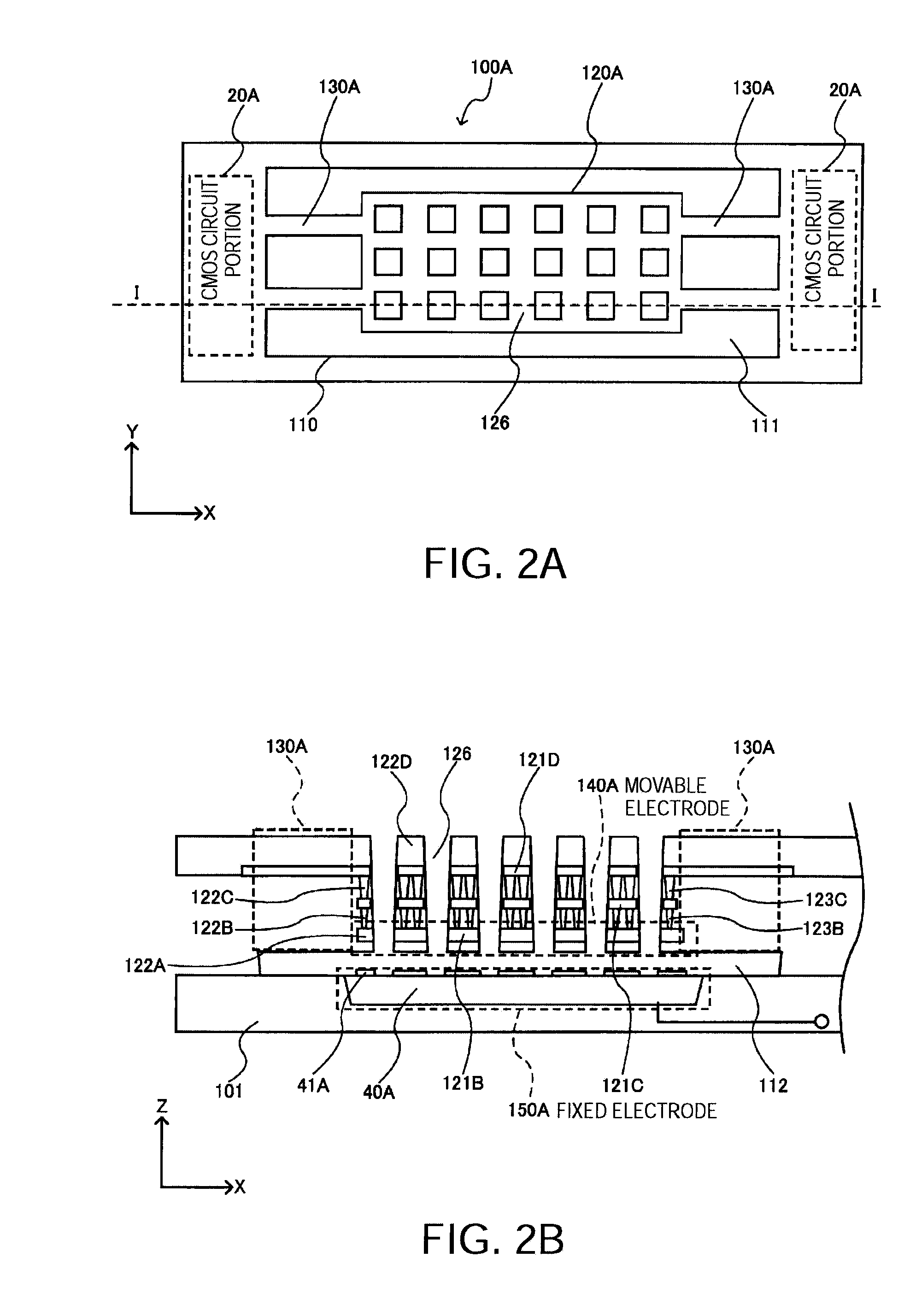
[0052]FIG. 1 is a schematic view of an acceleration sensor module 10A having mounted thereon a MEMS portion 100A according to the first embodiment to which a MEMS sensor of the invention is applied. The MEMS portion 100A according to the first embodiment has, for example, a movable weight portion 120A including a movable electrode portion 140A, a supporting portion 110 disposed around the movable weight portion 120A via first gap portions 111, a fixed electrode portion 150A having a facing-electrode face that faces a movable-electrode face of the movable electrode portion 140A via a second gap portion 112, and elastically deformable connecting portions 130A that support the movable weight portion 120A by coupling to the supporti...

second embodiment

2. Second Embodiment

[0101]With reference to FIGS. 18 to 22, a second embodiment of the invention will be described. In the following description, only the differences between the first embodiment and the second embodiment will be described. An acceleration sensor module 100B according to the second embodiment is a triaxial (X-, Y-, and Z-directions) acceleration sensor module to which the invention is applied. In the same manner as the first embodiment, a sensor chip and an IC chip can be integrally formed by a wafer process. In the second embodiment, the acceleration sensor 100B according to the embodiment has a movable weight portion 120B, different from the first embodiment where the MEMS portion 100A has the movable weight portion 120A.

[0102]The movable weight portion 120B is supported by a connecting portion 130B such that the movable weight portion can move in, in addition to the Z-direction orthogonal to the two-dimensional surface parallel to the substrate, at least one dire...


PUM

PropertyMeasurementUnit
Weightaaaaaaaaaa
Electrical conductoraaaaaaaaaa
Specific gravityaaaaaaaaaa

Abstract

A MEMS sensor includes: a substrate; a fixed electrode portion formed in the substrate; a movable weight portion formed above the fixed electrode portion via a gap; a movable electrode portion formed in the movable weight portion and disposed so as to face the fixed electrode portion; a supporting portion; and a connecting portion that couples the supporting portion with the movable weight portion and is elastically deformable, wherein the movable weight portion is a stacked structure having conductive layers and an insulating layer, and plugs having a larger specific gravity than the insulating layer are embedded in the insulating layer.

Description

BACKGROUND[0001]1. Technical Field[0002]The present invention relates to a MEMS (Micro Electro Mechanical System) sensor, a method of manufacturing the MEMS sensor, an electronic apparatus, and the like.[0003]2. Related Art[0004]As a silicon MEMS acceleration sensor with a CMOS integrated circuit for example, a reduction in size and cost for this type of MEMS sensor is rapidly progressing. The application and market of the MEMS sensor are expanding. In a main device form, an IC chip that converts a physical quantity into an electric signal and outputs the same is made into one package by a mounting process after a wafer process in most cases. For achieving an extreme reduction in size and cost, a technique of integrally forming a sensor chip and an IC chip by a wafer process is required (refer to JP-A-2006-263902).[0005]This type of MEMS sensor has such characteristics that sensitivity is enhanced as the mass of a movable weight portion increases. For increasing the mass of the mova...

Claims


Application Information

Patent Timeline
IPC IPC(8): H01L29/84H01L21/28B81B3/00B81C1/00G01P15/125G01P15/18
CPCB81B2201/0235B81B2203/0109G01P15/18G01P15/0802G01P15/125B81C1/00246G01P2015/082
Inventor TAKAGI, SHIGEKAZUSATO, AKIRA
Owner 138 EAST LCD ADVANCEMENTS LTD
Why Eureka
Try Eureka