Indirect Cooling of a Rotary Cutting Tool

a technology of cutting tool and cooling fluid, which is applied in the direction of shaping cutter, manufacturing tools, transportation and packaging, etc., can solve the problems of dermatitis and respiratory diseases, additives in cutting fluid may be carcinogenic, and the cost does not account for the health risks to which workers are exposed, so as to achieve the effect of easy integration with current manufacturing operations

Active Publication Date: 2010-10-28
5ME LLC
View PDF15 Cites 87 Cited by
  • Summary
  • Abstract
  • Description
  • Claims
  • Application Information

AI Technical Summary

Benefits of technology

[0010]The amount of cryogen needed for effective cooling is a function of the heat transfer rate to the tool during machining. The volumetric heat generation, qm, associated with a machining operation is expressed as;q″′=ψV∫Vɛ.σ_Vwhere {dot over (ε)}, σ, and V are the strain rate during machining, the material flow stress, and the volume of the strained material, known as the primary shear zone, respectively. The constant ψ represents the fraction of the deformation energy that is dissipated as sensible heating. For metals, the value of this constant is 0.8 or higher. The energy generated in the primary shear zone can be manifested as heating of the eventual chip after machining or be transferred to the tool. The fraction of heat flowing into the tool is a function of the tool geometry, the material, the machining conditions, and other variables. Established methods (analytical and computational) were used to estimate the maximum heat transfer rate into each cutting edge on the tool, qt. For the majority of conditions associated with machining advanced materials, the heat transfer rate was a maximum of 200 W per cutting edge. At atmospheric pressure, the latent heat of vaporization of liquid nitrogen (LN2) is approximately 180 Joules / gram. This implies that only 0.07 L / min (or 1.1 gram / sec) of LN2 is needed to dissipate the thermal energy per cutting edge if it can be delivered in close proximity to the cutting edge. Approximately ten times the flow rate of gaseous nitrogen (GN2) would be required to remove the same amount of heat with a temperature difference of 10 K. Thus, using LN2 minimizes the overall coolant flow requirements.
[0011]The cryogen is delivered from a fixed source, through a vacuum-insulated tube, and through other hardware mounted within the machine tool spindle, prior to reaching the tool. The cryogen is at a saturated condition as it leaves the source and flows toward the tool. A saturated condition means that any input of heat to the cryogen as it flows will result in the vaporization of some of the liquid to vapor. A key element of the components that are upstream of the tool itself is the minimization of heat transfer into the cryogen from the environment, also known as the heat leak into the cryogen. The heat leak can never be made to be zero; hence the flow after it leaves the source is known as a two-phase flow, where liquid and gas exist simultaneously. Minimizing the heat leak into the cryogen maximizes the liquid fraction in the two-phase flow, increases the amount of latent heat transfer at the cutter edge, and reduces the overall flow rates needed for effective cooling.
[0013]The invention is designed to be used with standard end mills and other rotary cutting tools; and as a result, it can be easily integrated with current manufacturing operations.

Problems solved by technology

This cost does not account for the health risks workers are exposed to when using these fluids.
Contact with cutting fluids or their mists can cause maladies such as dermatitis and respiratory diseases.
Some additives in cutting fluids may be carcinogenic.
However, this option increases fossil fuel consumption and energy costs because larger, and more powerful machines are required to process the less lubricious material.
Dry machining also increases the per part costs by consuming more cutting tools and requiring more machining time.
The problem is exacerbated when machining titanium or other low thermal conductivity materials since the heat produced at the tool-chip interface is not readily conducted away from the interface by the material itself.
Further, dry machining is not feasible for relatively small shop sites, where the capital for new machines is often not available.
Some degree of cooling was achieved, but the heat transfer efficiency of the design is very low.
No measurements of cutting tool flank wear reduction were made, possibly due to the poor performance of the system on the bench-top.
First, the jets require pressurized coolant using a large compressor that consumes electrical power, which increases the cost and environmental impact of the process.
Second, the jets need to be applied to particular locations on the cutting tool insert.
This approach is not feasible in a production environment, where the overhead associated with managing the high-pressure liquid jet quickly drives up the machining time and the costs.
Third, the high-pressure jets require liquid flow rates that are one to three orders of magnitude larger than the cooling system disclosed herein.
This fact dramatically increases the cost and the environmental impact of using high pressure jets.
Because the reservoir is located on top of the cutting tool insert, the device is difficult to use in a production environment.
These operations require special training, increasing costs, and increasing the health risks to operators.
For these reasons, it is unlikely that such a system would be used in a production environment, especially with a rotating tool.

Method used


Image

  • Indirect Cooling of a Rotary Cutting Tool
  • Indirect Cooling of a Rotary Cutting Tool
  • Indirect Cooling of a Rotary Cutting Tool

Examples


Embodiment Construction

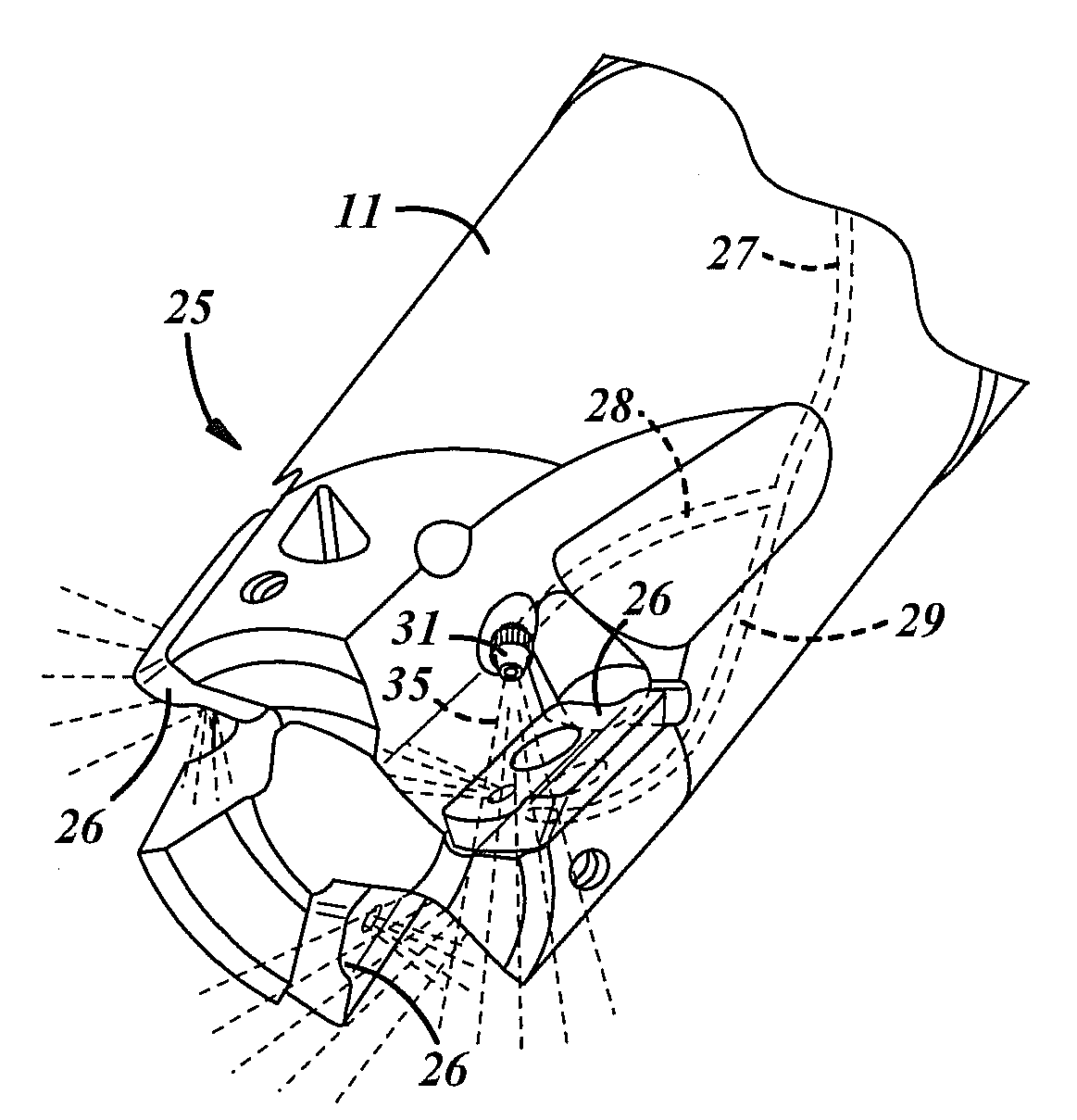
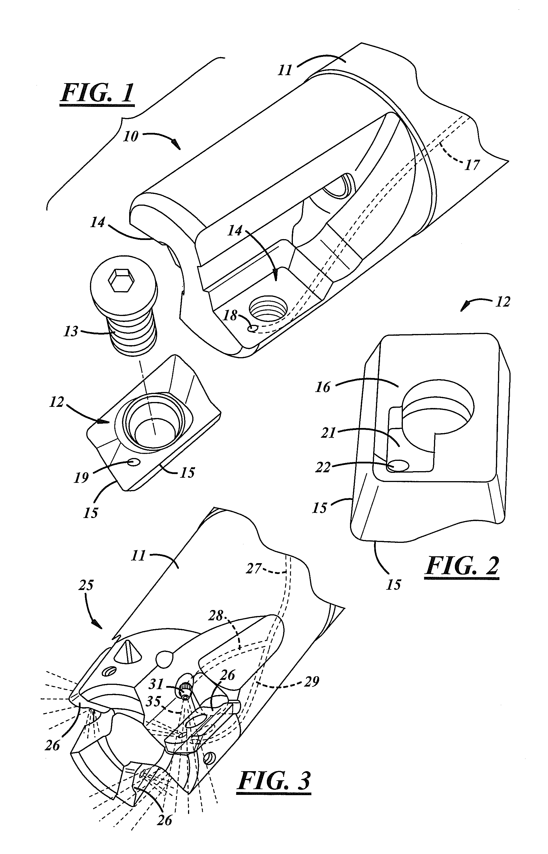
[0022]FIG. 1 shows the end of a rotary cutting tool, such as an end mill, generally designated by the reference numeral 10. An insert 12 may be secured in a pocket 14 in the end of the tool body 11 by a screw 13. The insert 12 has a cutting edge 15 that wraps around the corner of the insert. The particular milling cuter shown has two pockets 14 for receiving two inserts 12 that are disposed 180 degrees from one another, although end mills having pockets for receiving other numbers of inserts are well known in the art. Also, fluted end mills that have no inserts but have integrally formed flutes for cutting the workpiece, or cutting elements that are brazed or otherwise attached to the cutter body, are also well known in the art. Those practiced in the art of machining will appreciate that the indirect cooling system as described herein can apply to any rotating tool, with integral or attached cutting edges, or with inserts.

[0023]As shown in FIG. 1, the insert 12 is cooled indirectly...


PUM

PropertyMeasurementUnit
flow rateaaaaaaaaaa
temperatureaaaaaaaaaa

Abstract

An indirect cooling system for a rotating cutting tool uses a cryogenic coolant that is delivered to a cavity formed on the back surface of the cutting element, providing cooling near the cutting edge of the element. Because the total flow rate of the working fluid is low (less than 0.08 Liters / min / cutting edge), the fluid can be safely vented to atmosphere from the cavity, and as a result, no specialized coolant recovery or ventilation equipment is needed. The cavity may be formed with fins to enhance the heat transfer between the cutting element and the coolant, and coolant may additionally be sprayed directly onto the exterior surface of the element to cool the tool-chip interface. The indirect cooling system may be used for hard to machine metals and composites, as well as the machining of conventional materials without the use of traditional cutting fluids.

Description

[0001]This invention was made with Government support under Contract Nos. N00421-04-P-0547 and N68335-06-C-0069 awarded by the Department of the Navy. The Government has certain rights in the invention.FIELD [0002]A cooling system for the tool-chip interface of a rotary cutting tool uses both indirect and direct cooling of the cutter edge by a cryogenic fluid to enable the high-speed machining of titanium alloys and other advanced materials with low thermal conductivity.BACKGROUND [0003]Cutting fluids have been used in machining processes for many years to increase lubricity by spraying the coolant into the machining zone directly on the cutting tool and the workpiece. This has the effect of decreasing the friction between the chip and the tool, which in turn decreases the tool temperature, increases tool life, and improves the part quality. These benefits come with certain drawbacks. In high-volume machining operations, at least 16% of the machining cost is associated with the proc...

Claims


Application Information

Patent Timeline
Patent Type & Authority Applications(United States)
IPC IPC(8): B23B51/00
CPCB23C5/207B23C5/28B23C2200/165Y10T407/11Y10T407/118Y10T407/14Y10T408/44B23Q11/10B23Q11/1046B23Q11/1061Y02P70/10B23C5/202B23C5/22B23B27/10
Inventor ROZZI, JAY CHRISTOPHERSANDERS, JOHN KENDALLPASSOW, CHRISTIAN HENRYDAY, MICHAEL PHILLIPARCHIBALD, JR., EVERETT EDGAR
Owner 5ME LLC
Why Eureka
Try Eureka