Method and apparatus for sample extraction and handling

a sample and extraction method technology, applied in the field of sample extraction and handling, can solve the problems of destroying much consuming time, and affecting the quality of the original sample, and achieve the effect of increasing the throughput of tem analysis and less labor

a sample and extraction method technology, applied in the field of sample extraction and handling, can solve the problems of destroying much consuming time, and affecting the quality of the original sample, and achieve the effect of increasing the throughput of tem analysis and less labor

US20100305747A1Active Publication Date: 2010-12-02FEI CO

Image

  • Method and apparatus for sample extraction and handling
  • Method and apparatus for sample extraction and handling
  • Method and apparatus for sample extraction and handling

Examples


Embodiment Construction

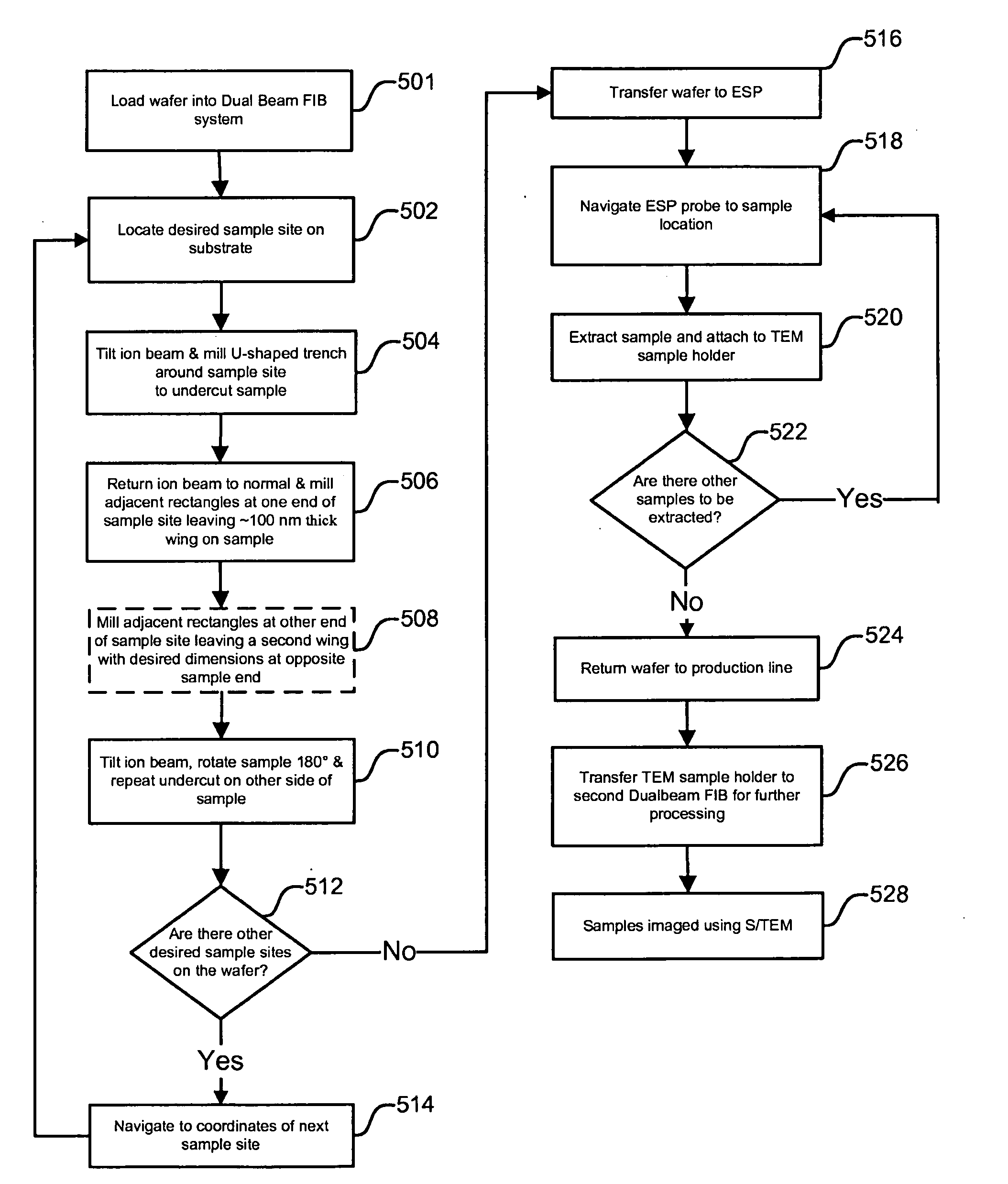
[0049]Preferred embodiments of the present invention provide a fully or partially automated process for TEM sample extraction and handling. Increased throughput and a less labor-intensive process will allow S / TEM based metrology to be better utilized in a wafer fabrication facility to provide rapid feedback to process engineers to troubleshoot or improve processes.

[0050]A preferred method or apparatus of the present invention has many novel aspects, and because the invention can be embodied in different methods or apparatuses for different purposes, not every aspect need be present in every embodiment. Moreover, many of the aspects of the described embodiments may be separately patentable.

[0051]In a preferred embodiment of the present invention, one or more lamellae are first created on a wafer or other substrate. Preferably, a number of lamellae can be created using an automated ex-situ process where a lamella is thinned in place before removal as described in U.S. Provisional App....


PUM


Abstract

An improved method and apparatus for extracting and handling samples for S / TEM analysis. Preferred embodiments of the present invention make use of a micromanipulator and a hollow microprobe probe using vacuum pressure to adhere the microprobe tip to the sample. By applying a small vacuum pressure to the lamella through the microprobe tip, the lamella can be held more securely and its placement controlled more accurately than by using electrostatic force alone. By using a probe having a beveled tip and which can also be rotated around its long axis, the extracted sample can be placed down flat on a sample holder. This allows sample placement and orientation to be precisely controlled, thus greatly increasing predictability of analysis and throughput

Description

[0001]The present application claims priority from U.S. Prov. Pat. App. No. 60 / 853,183, filed Oct. 20, 2006, and U.S. Prov. Pat. Appl. No. 60 / 927,719, filed on May 4, 2007, both of which are hereby incorporated by reference.TECHNICAL FIELD OF THE INVENTION[0002]The present invention relates to the extraction and handling of samples for transmission electron microscopes and scanning transmission electron microscopes.BACKGROUND OF THE INVENTION[0003]Semiconductor manufacturing, such as the fabrication of integrated circuits, typically entails the use of photolithography. A semiconductor substrate on which circuits are being formed, usually a silicon wafer, is coated with a material, such as a photoresist, that changes solubility when exposed to radiation. A lithography tool, such as a mask or reticle, positioned between the radiation source and the semiconductor substrate casts a shadow to control which areas of the substrate are exposed to the radiation. After the exposure, the photo...

Claims


Application Information

Patent Timeline
02 Dec 2010
Publication
US20100305747A1
IPC
H01J37/20; G06K9/00; B25J19/04; G05D3/12
CPC
G01N1/286; H01J2237/2812; G01N2001/2886; G01R31/2893; H01J37/26; H01J37/28; H01J37/31; H01J2237/2802
Inventors
AGORIO, ENRIQUE; HUDSON, JAMES EDGAR