Scintillator single crystal, heat treatment process for production of scintillator single crystal, and process for production of scintillator single crystal

a single crystal and scintillator technology, applied in the field heat treatment process for production of scintillator single crystal, can solve the problems of reducing the output of fluorescence, and the problem of reducing the output of a scintillator with a long fluorescent decay time combination, so as to reduce the difference in fluorescent output and reduce the output. the effect of long fluorescent decay time and easy

Inactive Publication Date: 2010-12-30
OXIDE
View PDF12 Cites 8 Cited by
  • Summary
  • Abstract
  • Description
  • Claims
  • Application Information

AI Technical Summary

Benefits of technology

[0031]According to this production process, it is possible to produce a scintillator single crystal with a sufficiently long fluorescent decay time to easily allow the difference in fluorescent decay times between two different scintillators that are combined to be 10 ns or greater.
[0032]According to the first aspect of the present invention, it is possible to provide a scintillator single crystal that can sufficiently reduce the difference in fluorescent output between the cerium low concentration and high concentration ends. Also according to the first aspect of the invention, it is possible to provide a scintillator single crystal with improved fluorescent output and energy resolution particularly at the cerium low concentration end which has a short decay time. According to the first aspect of the invention it is also possible to provide a heat treatment process for production of a scintillator single crystal that can sufficiently reduce the difference in fluorescent output between the cerium low concentration and high concentration ends, as well as a process for production of the scintillator single crystal.
[0033]According to the second aspect of the invention it is possible to provide a scintillator single crystal with a sufficiently long fluorescent decay time to easily allow the difference in fluorescent decay times between two different scintillators that are combined to be 10 ns or greater, as well as a process for production of the same.

Problems solved by technology

However, since the fluorescent output is reduced at the low cerium concentration end which has a short fluorescent decay time, the difference in output compared to a scintillator with a long fluorescent decay time combination is problematic from the standpoint of pulse shape discrimination of the energy spectrum.

Method used


Image

  • Scintillator single crystal, heat treatment process for production of scintillator single crystal, and process for production of scintillator single crystal
  • Scintillator single crystal, heat treatment process for production of scintillator single crystal, and process for production of scintillator single crystal
  • Scintillator single crystal, heat treatment process for production of scintillator single crystal, and process for production of scintillator single crystal

Examples


example 1

Production of Single Crystal

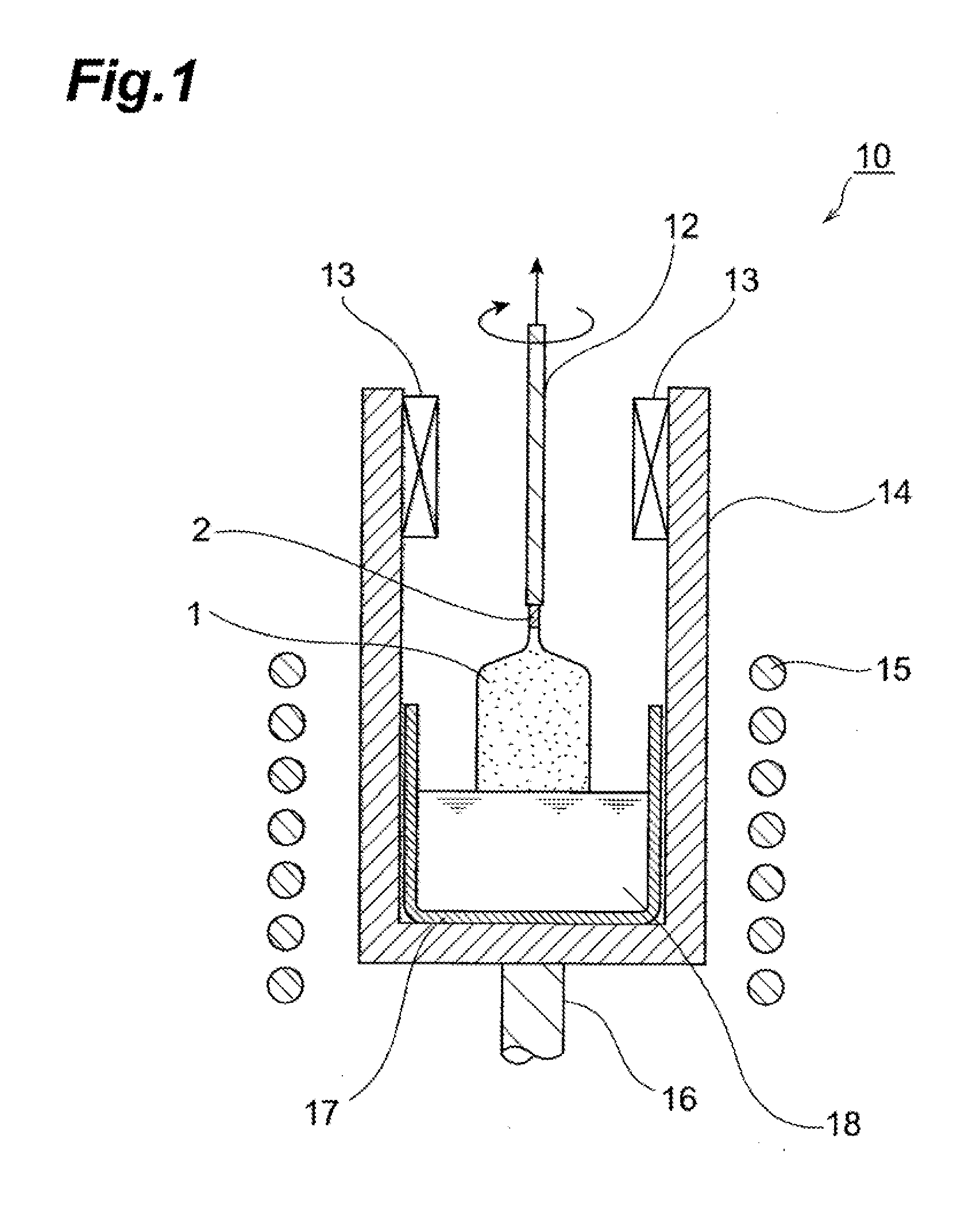
[0084]A single crystal was produced by the Czoehraski method. First, as the starting materials there were combined lutetium oxide (Lu2O3, 99.99 mass % purity), silicon dioxide (SiO2, 99.9999 mass % purity), cerium oxide (CeO2, 99.99 mass % purity) and praseodymium oxide (Pr6O11, 99.99 mass % purity) to a stoichiometric composition of Ln2−(x+y+z)LuxCeyLmzSiO5 (Ln=Lu, Lm=Pr, x=1.996, y=0.003, z=0.001), to obtain a total 500 g mixture. There was also weighed out 0.08748 g of calcium carbonate (CaCO3, 99.99 mass % purity) (corresponding to 0.007 mass % as Ca).

[0085]Next, the 500 g of obtained starting mixture and the weighed out calcium carbonate were loaded into an iridium crucible with a diameter of 50 mm, a height of 50 mm and a thickness of 1.5 mm, and heated in a high-frequency induction heating furnace to the melting point of approximately 2100° C. to obtain a melt. The melting point was measured using an electronic optical pyrometer (Pyrostar MODEL UR-...

example 2

[0093]A scintillator single crystal for Example 2 was produced in the same manner as Example 1, except that the amounts of lutetium oxide and cerium oxide in the starting material were adjusted so that x=1.996 was x=1.9985 and y=0.003 was y=0.0005. The fluorescent properties of the obtained scintillator single crystal were measured by the same procedure as for Example 1. Table 1 shows the compositional formula for this example and the results of measuring the fluorescent properties as averages for each sample.

example 3

[0094]A scintillator single crystal for Example 3 was produced in the same manner as Example 1, except that terbium oxide (Tb4O7, 99.99 mass % purity) was used instead of praseodymium oxide (Pr6O11, 99.99 mass % purity) (Lm=Tb) in the starting material. Based on the results of elemental analysis for the obtained single crystal ingot, the Tb segregation coefficient was 0.7, the Ce segregation coefficient was 0.25 and the Ca segregation coefficient was 0.15. The fluorescent properties of the obtained scintillator single crystal were measured by the same procedure as for Example 1. Table 1 shows the compositional formula for this example and the results of measuring the fluorescent properties as averages for each sample.


PUM

PropertyMeasurementUnit
temperatureaaaaaaaaaa
fluorescent wavelengthaaaaaaaaaa

Abstract

The scintillator single crystal of the invention comprises a cerium-activated orthosilicate compound represented by the following formula (1).
Gd2−(a+x+y+z)LnaLuxCeyLmzSiO5  (1)
(In formula (1), Lm represents at least one element selected from among Pr, Tb and Tm, Ln represents at least one element selected from among lanthanoid elements excluding Pr, Tb and Tm, and Sc, and Y, a represents a value of at least 0 and less than 1, x represents a value of greater than 1 and less than 2, y represents a value of greater than 0 and no greater than 0.01, and z represents a value of greater than 0 and no greater than 0.01. The value of a+x+y+z is no greater than 2.)

Description

BACKGROUND OF THE INVENTION[0001]1. Field of the Invention[0002]The present invention relates to a scintillator single crystal used in a single-crystal scintillation detector (scintillator) for gamma ray or other radiation in the fields of radiology, physics, physiology, chemistry, mineralogy and oil exploration, such as for medical diagnostic positron CT (PET), cosmic radiation observation, underground resource exploration and the like, as well as to a heat treatment process for production of a scintillator single crystal and to a process for production of a scintillator single crystal. More specifically, the invention relates to a scintillator single crystal comprising a cerium-activated orthosilicate compound, to a heat treatment process for production of a scintillator single crystal, and to a process for production of a scintillator single crystal.[0003]2. Related Background Art[0004]Scintillators composed of gadolinium orthosilicate compounds with cerium as the activator have ...

Claims


Application Information

Patent Timeline
Patent Type & Authority Applications(United States)
IPC IPC(8): C09K11/79
CPCC09K11/7792C30B33/02C30B29/34C30B15/00C09K11/77742
Inventor KURATA, YASUSHIUSUI, TATSUYASHIMURA, NAOAKI
Owner OXIDE
Why Eureka
Try Eureka