
Stress Induced Crystallographic Phase Transformation and Texturing in Tubular Products Made of Cobalt and Cobalt Alloys

a technology of stress-induced crystallographic phase transformation and texturing, which is applied in the field of tubular components, can solve the problems of catastrophic burst of barrels, increased brittleness, and dangerous high-heavy brittle materials in gun barrels

Active Publication Date: 2011-01-20
ATI FLOWFORM PROD
View PDF16 Cites 16 Cited by
  • Summary
  • Abstract
  • Description
  • Claims
  • Application Information

AI Technical Summary

Benefits of technology

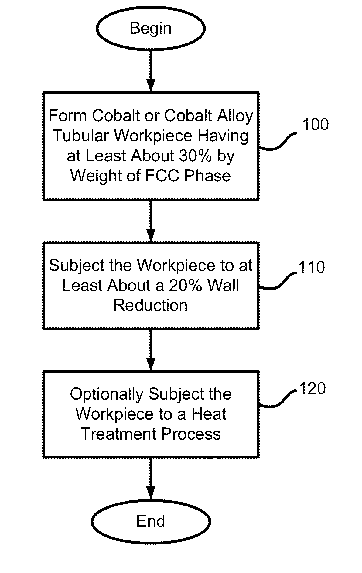
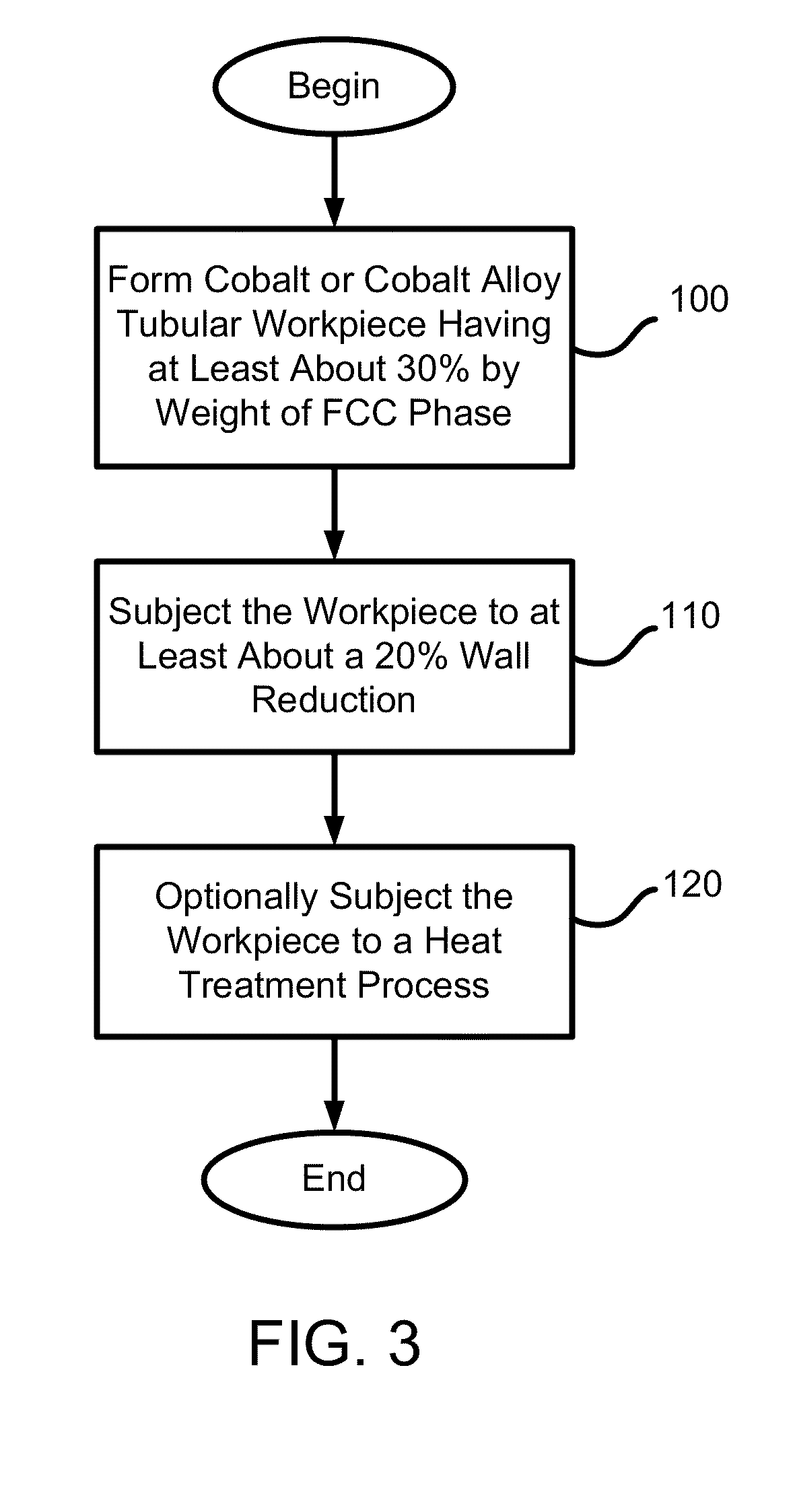
[0010]In accordance with one embodiment of the invention, a method of producing a cobalt-based tubular product includes forming a cobalt or cobalt alloy tubular workpiece having at least about 30% by weight of fcc phase, and subjecting the workpiece to at least about a 20% wall reduction at a temperature below a recrystallization temperature of the workpiece using a metal forming process. The metal forming process may include radial forging, rotary swaging, pilgering and / or flowforming.

Problems solved by technology

However, the trade-off for attaining high strength by heat treatment in steel alloys is an increase in brittleness.
A high strength brittle material in a gun barrel is dangerous because overpressure caused by a plugged barrel or excessive powder loads, or weakness in the barrel caused by damage, fatigue, corrosion, or other such factors could cause the barrel to burst catastrophically instead of just bulge.
Since the bursting usually occurs at the breech end, near the shooter's face, the potential for serious injury, blinding, or death is more likely with brittle materials.
As a result, the barrel wall thickness must be made commensurably thicker and the “soft” condition of the barrel material is susceptible to rapid erosion on the inside diameter of the barrel from the passage of the projectiles.
Corrosion resistance of high carbon steels is notoriously poor.
However, such coatings are most useful if applied frequently, especially immediately after each use of the gun, but it is rarely convenient to do so.
Consequently, there is a period following use of the gun before it is cleaned and coated with the protective coating during which rapid corrosion can occur, especially since the combustion products of the propellant, and the projectile fragments remaining in the barrel can create galvanic corrosion.
The resultant pitting of the bore then tends to trap additional corrosive materials, further exacerbating the corrosive effects.
Hot plastic deformation of a conventional steel barrel is a serious problem, especially in weapon systems.
In this case, the projectile is loose in such an over-sized bore and results in poor accuracy for the gun.
Moreover, the blow-by of propellant gases around the projectile in the bore is so great that the projectile does not develop the velocity it needs to attain its specified range, and instead falls short of its intended target.
The limitations of this technique are the burst strength of the barrel, primarily in the breech area when the barrel is hot.
Such conventional thick walled steel gun barrels are very heavy and have a tendency to droop at the muzzle end when aimed at low elevations.
In addition, the barrel becomes hot from aggressive firing and the Young's modulus of the steel drops.
This has been an intractable problem in the past because of the need for high burst strength and the high density of the only known materials that were proven for use in gun barrels.
Second, cobalt alloys have sufficient shear strength high enough to resist the reaction forces of the projectile on the lands of the rifled M242 barrel.
It was estimated that pure tantalum would not have a high enough strength to be used in the M242 barrel.
In contrast, difficulties have been experienced in machining an explosively-clad tantalum alloy in an M242 Bushmaster barrel.
The cobalt liners eventually fail due to fatigue from the combination of repetitive firing pulses, extreme heat and pressure and also fail due to wear from the abrasiveness of the existing projectiles.

Method used


Image

  • Stress Induced Crystallographic Phase Transformation and Texturing in Tubular Products Made of Cobalt and Cobalt Alloys
  • Stress Induced Crystallographic Phase Transformation and Texturing in Tubular Products Made of Cobalt and Cobalt Alloys
  • Stress Induced Crystallographic Phase Transformation and Texturing in Tubular Products Made of Cobalt and Cobalt Alloys

Examples


Embodiment Construction

[0010]In accordance with one embodiment of the invention, a method of producing a cobalt-based tubular product includes forming a cobalt or cobalt alloy tubular workpiece having at least about 30% by weight of fcc phase, and subjecting the workpiece to at least about a 20% wall reduction at a temperature below a recrystallization temperature of the workpiece using a metal forming process. The metal forming process may include radial forging, rotary swaging, pilgering and / or flowforming.

[0011]In accordance with related embodiments, the temperature of the metal forming process may be around room temperature. The method may further include annealing the workpiece after subjecting the workpiece to the wall reduction. The method may further include forming a rifling on an inner diameter of the workpiece. When the metal forming process is flowforming, the flowforming may include at least two flowforming passes and the workpiece may be annealed between the flowforming passes. The workpiece...


PUM

PropertyMeasurementUnit
temperaturesaaaaaaaaaa
inner diameteraaaaaaaaaa
grain sizeaaaaaaaaaa

Abstract

A method of producing a cobalt-based tubular product includes forming a cobalt or cobalt alloy tubular workpiece having at least about 30% by weight of fcc phase and subjecting the workpiece to at least about a 20% wall reduction at a temperature below a recrystallization temperature of the workpiece using a metal forming process. The metal forming process may include radial forging, rotary swaging, pilgering and / or flowforming. A gun barrel includes a tubular component made of a cobalt-based superalloy material. The component has at least about 25% by weight of hcp phase with basal planes radially oriented perpendicular to an inner diameter of the component.

Description

CROSS-REFERENCE TO RELATED APPLICATIONS[0001]This patent application claims priority to U.S. Provisional Patent Application No. 61 / 181,042 filed May 26, 2009, entitled STRESS INDUCED CRYSTALLOGRAPHIC PHASE TRANSFORMATION AND TEXTURING IN TUBULAR PRODUCTS MADE OF COBALT AND COBALT ALLOYS, and claims priority to U.S. Provisional Patent Application No. 61 / 302,778 filed Feb. 9, 2010, entitled SYSTEM AND METHOD OF PRODUCING AUTOFRETTAGE IN TUBULAR COMPONENTS USING A FLOWFORMING PROCESS, the disclosures of which are incorporated by reference herein in their entirety.TECHNICAL FIELD[0002]The invention generally relates to tubular components and, more particularly, the invention relates to tubular products made of cobalt and cobalt alloys.BACKGROUND ART[0003]Gun barrels have been made in substantially the same way since the early 1900's, with only minor improvements in processes and materials since then. Conventional steel alloys used in gun barrels, including rifles, side arms, and shotgun...

Claims


Application Information

Patent Timeline
Patent Type & Authority Applications(United States)
IPC IPC(8): F41A21/00F16L9/02B21C37/30B21K21/00
CPCF41A21/20B21J5/00
Inventor FONTE, MATTHEW V.
Owner ATI FLOWFORM PROD
Learn More