Hollow nanofibers-containing composition

a technology of composition and hollow nanofiber, which is applied in the field of hollow nanofiber, hollow nanofiber, and catalyst composition for manufacturing hollow nanofiber, can solve the problems of many impurities such as amorphous carbon, the inability to reduce the detection of graphite layer, and the carbon nanotube obtained. to achieve the effect of facilitating separation and removal of the produced carbon nanotub

Inactive Publication Date: 2011-02-03
SHINOHARA HISANORI +4
View PDF4 Cites 34 Cited by
  • Summary
  • Abstract
  • Description
  • Claims
  • Application Information

AI Technical Summary

Benefits of technology

[0023]Thus, by using the membranous zeolite in place of a powdered zeolite, it is possible to reuse the zeolite which is a supporting material, and to facilitate separation and removal of the produced carbon nanotube from the zeolite.
[0024]Moreover, according to each of the manufacturing methods of the present invention, it is possible to obtain novel...

Problems solved by technology

The carbon nanotubes obtained by the aforementioned arc discharge method have a drawback that there are many impurities such as amorphous carbon though the number of graphite layer defects is small.
However, the carbon nanotubes manufactured by the CVD method have a problem that there are many defects on a graphite layer, and thus the graphite layer detects cannot be reduced unless heat treatment of about 2900° C. is carried out in a post process.
However, in order to obtain thin single-walled nanotubes by the aforementioned method, reaction must be carried out at a high temperature of 800 to 900° C. When the carbon nanotubes are produced at a temperature exceeding 800° C., there has been a problem that a structural change occurs in a zeolite of a catalyst supporting material during reaction to cause aggregation of a metal carried on the zeolite, and consequently stable production of thin and good-quality single-walled carbon nanotubes become difficult.
Additionally, the single-walled carbon nanotubes are useful because of these thin shape, but there is a problem that durability is low due to a one-layer structure.
Howeve...

Method used


Image

  • Hollow nanofibers-containing composition
  • Hollow nanofibers-containing composition
  • Hollow nanofibers-containing composition

Examples


example 1

Synthesis of Thermal Resistant Zeolite

[0154]Distilled water (164 g) was added to piperazinehexazhydrate (made by Aldrich) (18.9 g) and tetrapropylammonium bromide (made by Aldrich) (5.2 g), and it was agitated. The agitation was continued until dissolution while heating. Then, fumed silica (made by Aldrich) (11.7 g) was further added, and heating was executed up to 80° C. to obtain a transparent aqueous solution. This was put into an autoclave of poly 4-ethylene fluoride line, and heated at 150° C. for five days. Subsequently, the sample was cooled, filtered, washed by water, and dried, and then calcined at 550° C. in air.

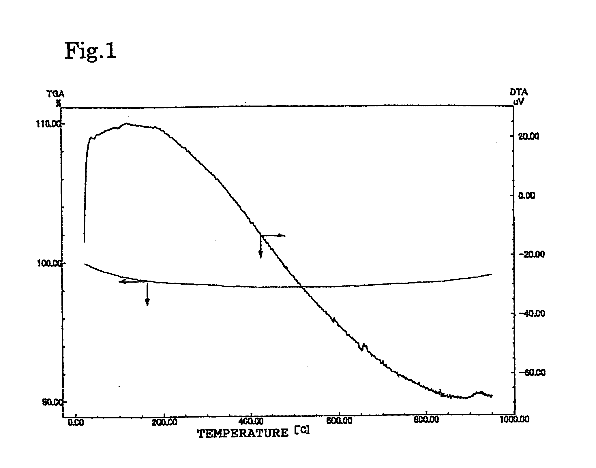
[0155]X-ray diffraction (XRD) of obtained powder was measured to find that the sample was silicalite-1 having an MFI type structure. These powders were heated to 900° C. at a temperature rising rate of 5° C. / min, in a gas flow of nitrogen 50 ml / min, by Shimadzu Corporation's thermal analyzer, and no exothermic peak appears in a DTA curve (FIG. 1).

Carrying of Metal ...

example 2

Heat Resistance of Crystalline Titanosilicate

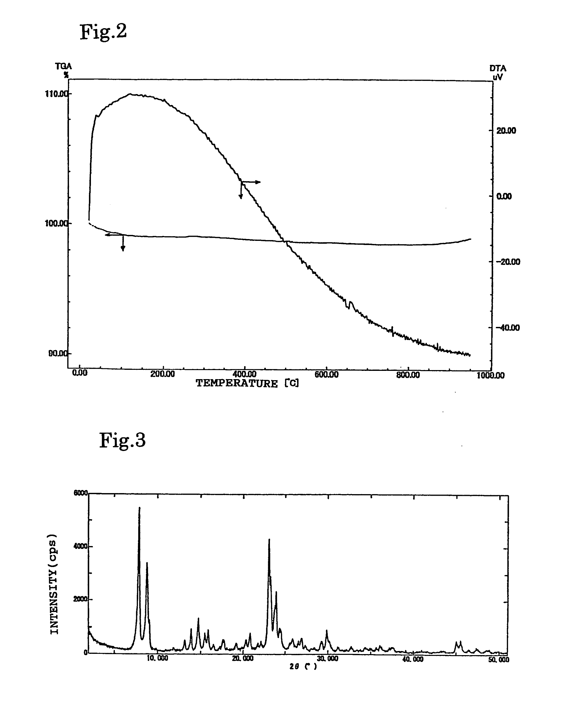
[0160]Titanosilicate powder (TS-1; Si / Ti ratio was 50) bought from NE Chemcat Corporation was subjected to X-ray diffraction (XRD) measurement to find TS-1 having an MFI type structure. These powders were heated to 900° C. at a temperature rising rate of 5° C. / min, in a gas flow of nitrogen 50 ml / min, by Shimadzu Corporation's thermal analyzer DTG-50, and no exothermic peak appeared in a DTA curve (FIG. 2).

[0161]This zeolite was calcined at 900° C. for 30 minutes, and then subjected to XRD diffraction to find a residual peak of the MFI type zeolite (FIG. 3).

Carrying of Metal Salt on Thermal Resistant Zeolite

[0162]Ferrous acetate (made by Aldrich) (0.08 g) and cobalt acetate 4 hydrate (made by Nacalai Tesque, Inc.) (0.11 g) were added to methanol (made by Nacalai Tesque, Inc.) (7 ml), and suspended by an ultrasonic cleaner for 10 minutes. Powder (1.0 g) of the TS-1 was added to this suspension, and the suspension was treated by the ultraso...

examples 3 , 4

Examples 3, 4

Comparative Example 2

[0183]A zeolite HSZ-390HUA (zeolite 1) of Tosoh Corporation was heated up to 900° C. at a temperature rising rate of 5° C. / min, in a gas flow of nitrogen 50 ml / min, by Shimadzu Corporation's thermal analyzer DTG-50. As a result, an exothermic peak appeared in a DTA curve (FIG. 11).

[0184]This zeolite was subjected to XRD measurement after burning in dry air at 900° C. for 30 minutes. A structure of a Y type zeolite was held, but a peak was sharper and larger than that before the burning (XRD before burning: FIG. 13, XRD after burning: FIG. 14). A certain structural change may have occurred during heating up to 900° C.

[0185]The zeolite HSZ-390HUA (zeolite 2) burned at 900° C. for 30 minutes, was heated up to 900° C. at a temperature rising rate of 5° C. min, in a gas flow of nitrogen 50 ml / min by Shimadzu Corporation's thermal analyzer DTG-50. As a result, change occurred so as to prevent appearance of an exothermic peak in a DTA curve (FIG. 12).

[0186...


PUM

PropertyMeasurementUnit
Nanoscale particle sizeaaaaaaaaaa

Abstract

A method for preparing hollow nanofibers having carbon as a primary component by contacting a carbon-containing compound with a catalyst at 500 to 1200° C., wherein the catalyst is one of a zeolite exhibiting thermal resistance at 900° C. and, supported thereon, a metal; a metallosilicate zeolite containing a heteroatom except aluminum and silicon and a metal; a supporting material and fine cobalt particles exhibiting a binding energy of a cobalt 2P3/2 electron of 779.3 to 781.0 eV; a supporting material and fine cobalt particles exhibiting a cobalt atom ratio in the surface of the supporting material of 0.1 to 1.5%, as measured by the X-ray photoelectron spectroscopy at 10 kV and 18 mA; a supporting material and fine cobalt particles exhibiting a weight ratio of cobalt to a second metal component of 2.5 or more; and a zeolite having a film form and a metal.

Description

[0001]This application is a division of application Ser. No. 10 / 496,836, filed May 27, 2004, which is a 371 of international application PCT / JP02 / 12445, filed Nov. 28, 2002, which claims priority based on Japanese Patent Application Nos. 2001-361992 and 2001-372718, filed Nov. 28, 2001, and Dec. 6, 2001, respectively, and which are incorporated herein by reference.TECHNICAL FIELD[0002]The present invention relates to a method for manufacturing hollow nanofibers, hollow nanofibers, and a catalyst composition for manufacturing hollow nanofibers. More particularly, the present invention relates to a method for manufacturing hollow nanofibers which enables acquisition of a thin and multi-walled carbon nanotube having a small number of graphite layer defects, hollow nanofibers obtained by this method, and catalyst composition for manufacturing hollow nanofibers.BACKGROUND ART[0003]A representative example of hollow nanofibers is carbon nanotubes. The carbon nanotubes have cylindrical sha...

Claims


Application Information

Patent Timeline
IPC IPC(8): D01F9/12B01J29/072B01J29/14B01J29/46B01J29/86B01J29/88B01J29/89B01J35/06B82Y30/00C01B31/02D01F9/127
CPCB01J29/046D01F9/127B01J29/146B01J29/46B01J29/86B01J29/88B01J29/89B01J35/065B01J2229/186B82Y30/00B82Y40/00C01B31/0233C01B2202/02C01B2202/04C01B2202/06C01B2202/34C01B2202/36B01J29/072C01B32/162B82B1/008
Inventor SHINOHARA, HISANORIYOSHIKAWA, MASAHITOOZEKI, YUJIOKAMOTO, ATSUSHIKUROKI, MOTOHIRO
Owner SHINOHARA HISANORI
Why Eureka
Try Eureka