Low energy portable low-light camera with wavelength cutoff

a low-energy, portable technology, applied in the direction of solid-state devices, instruments, material analysis, etc., can solve the problems of limited performance of night vision devices, limited semiconductor materials, and low amount of light available on moonless nights, so as to maximize the detection of moonless night sky illumination, minimize dark current, and optimize spectral response

Active Publication Date: 2011-03-03
EOTECH LLC
View PDF18 Cites 16 Cited by
  • Summary
  • Abstract
  • Description
  • Claims
  • Application Information

AI Technical Summary

Benefits of technology

[0028]The In1-xGaxAsyP1-y composition is chosen to optimize spectral response of the In1-xGaxAsyP1-y to maximize detection of moonless night sky illumination while minimizing dark current generated in the In1-xGaxAsyP1-y absorber layer.

Problems solved by technology

The low amount of light available on moonless nights provides the greatest challenge to Night Vision image sensors.
Night Vision device performance is limited by the amount of available light on moonless nights.
Dark noise is dominated by thermally generated dark current in a high performance sensor.
The combination of these requirements on the photosensing element limits the choice of semiconductor materials for the photocathode or photodiode and specifies image sensor operating temperature.
However these FPAs have performance, size, and power constraints that limit their applicability to manportable night vision systems.
Larger FPAs would increase system size and cost to unacceptable levels for manportable applications.
The smaller array size limits system resolution and object detection range for the desired large field of view systems used for manportable night vision.
The provision of cooling for portable applications places a high demand on batteries, thereby reducing the useful operational time of the device before batteries are emptied.
This level of cooling substantially increases system size and power requirements making the approach unsuitable for battery operated night vision applications.
These cooling requirements limit application of these SWIR image sensors to battery operated applications due to high power requirements for focal plane cooling.

Method used


Image

  • Low energy portable low-light camera with wavelength cutoff
  • Low energy portable low-light camera with wavelength cutoff
  • Low energy portable low-light camera with wavelength cutoff

Examples


Embodiment Construction

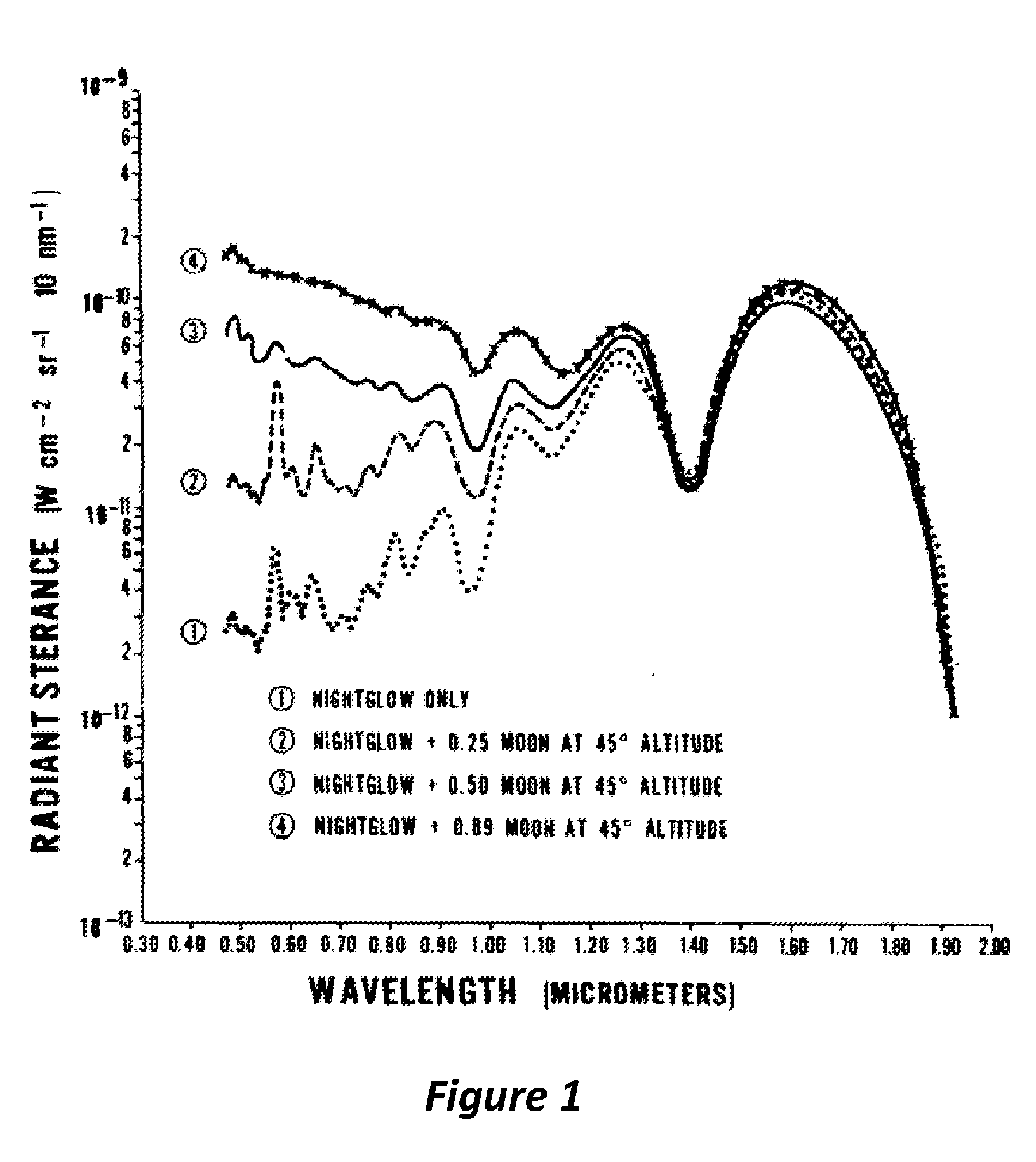
[0037]FIG. 1 shows the spectral intensity of the night sky illumination as a function of wavelength. This data is disclosed by Vatsia, Mirshri, L. “Atmospheric Optical Environment”, Research and Development Technical Report ECOM-7023, September (1972). Curve 1 on this graph plots the illumination level versus wavelength on a moonless night. This represents the darkest, most challenging, condition for operation of a night vision device. It can be observed that there is a large reduction in the available light at night in the 1.4 to 1.5 μm wavelength range. This reduction is caused by absorption of optical radiation in this band by water in the atmosphere. On the other hand, there is a second “maxima” beyond 1.4 μm, centered at about 1.63 μm. Therefore, artisans in the art have sought to develop sensors that have long wavelength cutoff beyond 1.7 μm, so as to capture this second maxima. Conversely, embodiments of this invention restrict the long wavelength cutoff of the semiconductor ...


PUM


Abstract

A sensor for night vision applications is provided, wherein the sensor comprises a semiconductor absorption layer of composition that limits long wavelength response cutoff to between 1.25 to 1.4 μm wavelength. The selection of this cutoff frequency provides improved dark current performance, thereby requiring less cooling of the sensor. Consequently, energy consumption is reduced, as the sensor does not require active cooling, so that the sensor is particularly beneficial for mobile night vision applications where battery weight is of high importance.

Description

RELATED APPLICATIONS[0001]This Application claims priority benefit from U.S. Provisional Application Ser. No. 61 / 238,641, filed Aug. 31, 2009, the entire disclosure of which is incorporated herein by reference.BACKGROUND[0002]1. Field of Invention[0003]This invention relates to the field of Low Light Level Imaging for Night Vision Applications.[0004]2. Related Art[0005]Photocathode based image intensifier tubes, Electron Bombarded CCDs (EBCCD), and Electron Bombarded Active Pixel Sensors (EBAPS) are well known for the purpose of acquiring images under low light level illumination conditions. EBAPS are described in U.S. Pat. No. 6,285,018 B1. EBCCDs are described in U.S. Pat. No. 4,687,922. These photocathode based devices employ a wide array of photocathode materials ranging from traditional multi-alkali or bi-alkali photocathodes used in so called Generation-II image intensifiers to modern negative electron affinity (NEA) III-V semiconductor photocathodes using GaAs, GaAs1-xPx (lat...

Claims


Application Information

Patent Timeline
Patent Type & Authority Applications(United States)
IPC IPC(8): H01L25/00
CPCH01L27/14643H01L31/0304H01L27/1464H01L31/109Y02E10/544H01L31/03046
Inventor AEBI, VERLE W.
Owner EOTECH LLC
Why Eureka
Try Eureka