Signal conditioner with suppression of interfering signals

a signal conditioner and signal technology, applied in the field of signal conditioners, can solve the problems of inability to fully meet the low cost demand, the inability to remove acoustic noise in the audio band (also denoted in-band noise), and the inability to completely damage the desired audio signal, so as to improve the achievable gain of the preamplifier, improve the achievable signal quality, and improve the effect of amplitud

Inactive Publication Date: 2011-03-03
INVENSENSE
View PDF28 Cites 38 Cited by
  • Summary
  • Abstract
  • Description
  • Claims
  • Application Information

AI Technical Summary

Benefits of technology

[0059]When the digital signal processor is configured with a digital low-pass filter, the signal conditioner implements a high-pass filter to suppress low frequency signals from the transducer. This will prevent the amplifier from overloading at its output (which would result in clipping of the output signal) when the transducer is exposed to acoustical signals, thermal signals or movements (vibrations) with large undesired low-frequency signal components. Overloading of the input is generally not as big a problem as output overloading since the input signal has not been amplified and thus has lower amplitude than the output signal.
[0060]The feedback circuit can be implemented as a low-pass filter so as to provide high-pass filter transfer function of the signal conditioner. The signal from the transducer and the feedback signal are provided at two different terminals of the gain stage. The two different terminals of the gain stage are coupled to each other e.g. like the drain and gate of a CMOS transistor are coupled or like the gates of a pair of transistors in a differential gain stage are coupled. Thereby the input terminal at which the signal from the capacitive transducer is received is protected from low or varying impedance of the feedback circuit or network. Thus, since the transducer signal input to the gain stage is not exposed to the only slowly decaying impulse

Problems solved by technology

However, since the analogue feedback filter occupies a substantial area on a chip die, the demands in terms of low cost cannot be fully met.
Further, due to the fixed structure of the filter, its filter properties cannot be changed e.g. its characteristic poles and zeroes cannot be changed.
Moreover, acoustic noise present in the audio band (also denoted in-band noise) cannot be removed without damaging a desired audio signal severely.
The amplifier circuit is configured with fixed filter properties of the feedback system and is not suitable for being changed during operation.
This configuration is a low-cost analogue-to-digital converter, which provides only weak shaping of switching noise introduced by the comparator and hence only a poor signal-to-noise ratio is achievable.
Further, the converter does not provide means to filter an input signal in the frequency range where the system operates as an analogue-to-digital converter.
Consequently, the converter is not suited for enhancing a desired signal relative to an undesired signal that interferes with the desired signal.
Since the converter is basically an analogue converter, although non-linear processing is used, the converter i

Method used


Image

  • Signal conditioner with suppression of interfering signals
  • Signal conditioner with suppression of interfering signals
  • Signal conditioner with suppression of interfering signals

Examples


Embodiment Construction

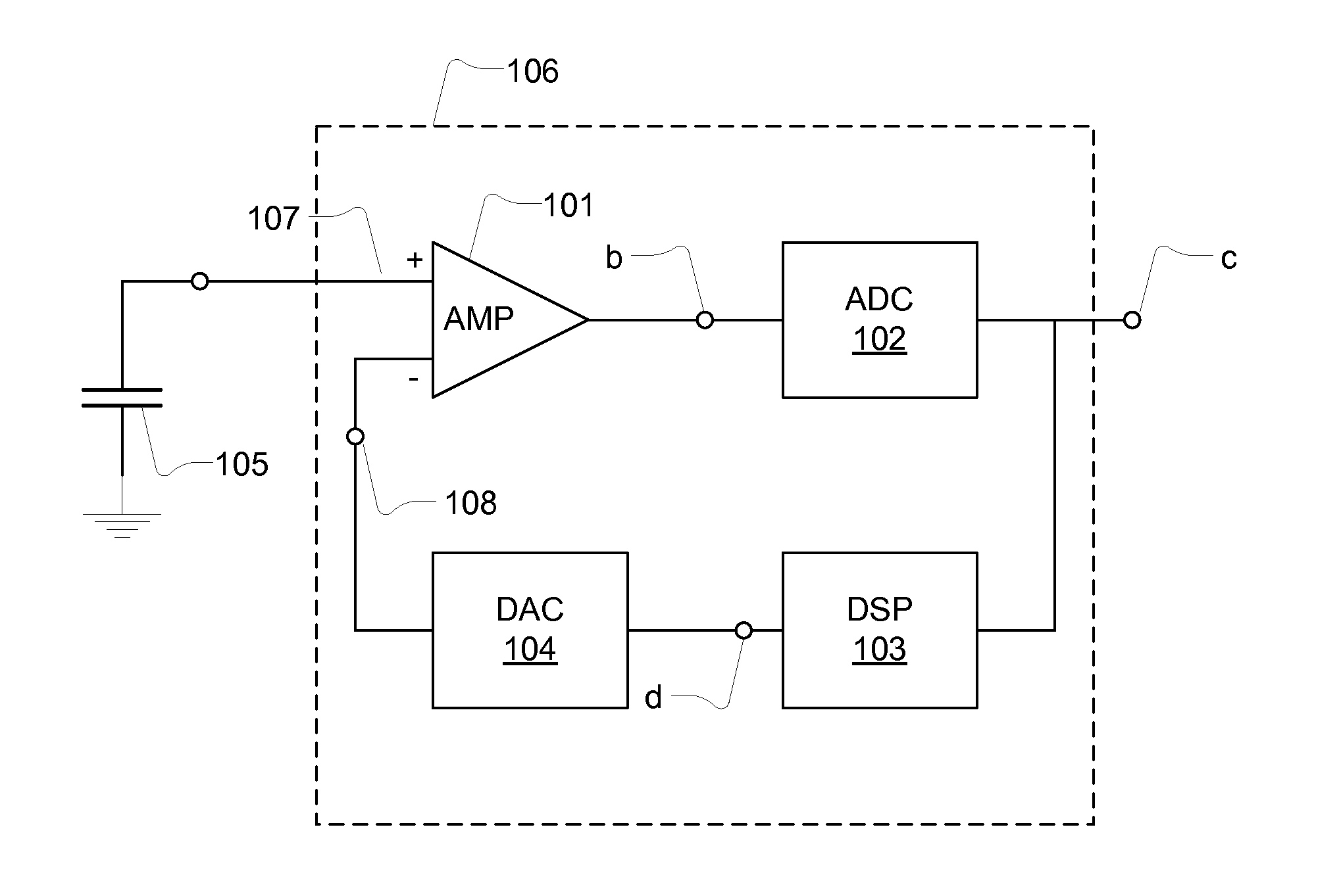
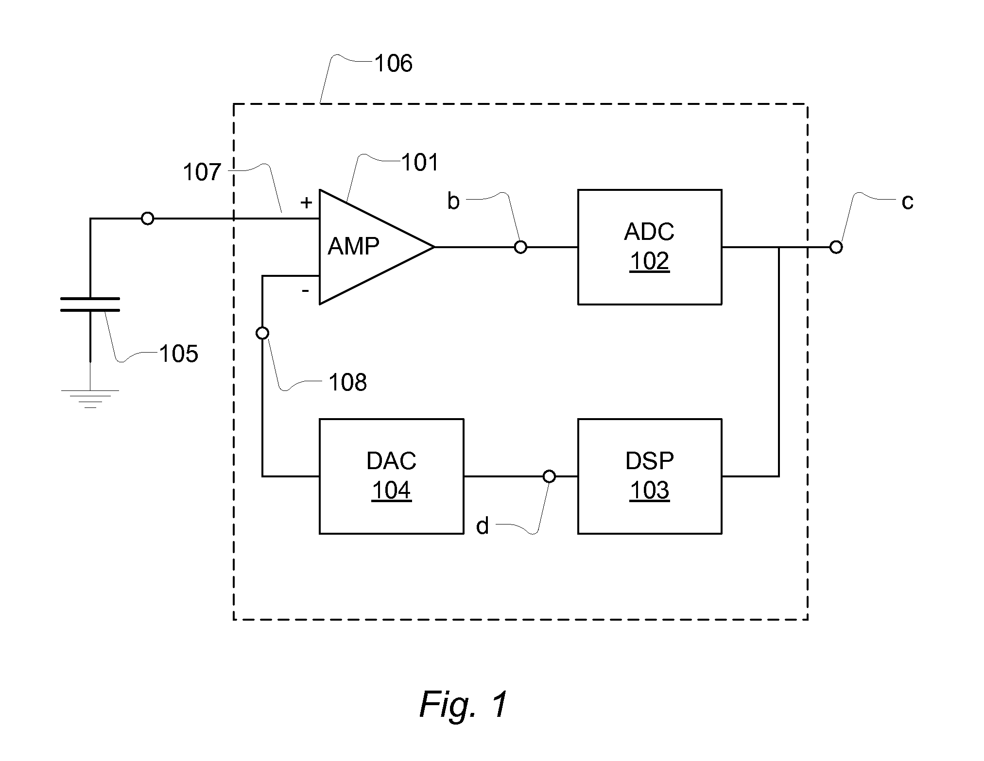
[0086]FIG. 1 shows a transducer and a signal conditioner 106. The transducer is a capacitive transducer 105 e.g. forming part of a condenser microphone. The capacitive transducer 105 converts a type of energy e.g. a sound pressure to an analogue electrical signal. The analogue transducer signal may comprise a desired signal and an interfering or undesired signal. The capacitive transducer 105 is coupled to a gain stage in form of preamplifier AMP, 101 that has an output terminal and a non-inverting input terminal 107 and an inverting input terminal 108 which is coupled to a feedback signal provided by a digital-to-analogue converter 104. The preamplifier is configured to receive input signals at the input terminals as a differential input and provide the output signal in response to the differential input. In general the preamplifier 101 is characterized by differential inputs that exhibit high input impedance compared to the output impedance at the output terminal. In an open loop ...


PUM


Abstract

A semiconductor die with an integrated circuit providing a signal conditioner (106) for a capacitive transducer (105), comprising: a gain stage (101) configured to receive an analogue transducer signal; an analogue-to-digital converter (102) coupled to receive a signal outputted from the gain stage (101) and to provide a digital signal. A feedback signal is provided via a digital-to-analogue converter (104) and a digital signal processor (103) that receives the digital signal; and the gain stage (101) is configured with a first input (107) and second input (108) coupled to receive the analogue transducer signal and the feedback signal, respectively.

Description

FIELD OF THE INVENTION[0001]A signal conditioner, for a transducer, embodied on a semiconductor die with an integrated circuit comprising a preamplifier, an analogue-to-digital converter and a feedback configuration is disclosed.BACKGROUND[0002]A transducer acts to convert a type of energy e.g. acoustical into electrical energy—a signal is converted into an electrical signal. The electrical signal however typically needs some type of electrical signal processing to bring it into a desired form—this is also denoted signal conditioning. A signal conditioner for a transducer acts as an intermediate signal processing stage between a transducer and any subsequent stage.[0003]Signal conditioners for transducers are often made especially for a specific type of transducer and a specific application since, often, the signal conditioner has to meet special operating conditions set by both the type of transducer and its application. The particular operating conditions can be seen as physical l...

Claims


Application Information

Patent Timeline
IPC IPC(8): H04B15/00
CPCH03F2200/321H03F3/34H03M1/00H03M1/181H03M1/183H04R1/04H04R3/00H04R3/06H04R25/505H04R2499/11
Inventor THOMSEN, HENRIKFURST, CLAUS ERDMANN
Owner INVENSENSE
Why Eureka
Try Eureka