Method for cancer detection, diagnosis and prognosis

a cancer and prognosis technology, applied in the field of cancer detection, diagnosis and prognosis, can solve the problems of ctc detection, ctc isolation and (2), requiring expensive reagents and equipment, and a relatively small population of ctcs, and achieves rapid and efficient capture of circulating tumor cells, greater than 90% cell viability, and greater capture efficiency

Active Publication Date: 2011-03-03
UNIV OF SOUTHERN CALIFORNIA +1
View PDF7 Cites 87 Cited by
  • Summary
  • Abstract
  • Description
  • Claims
  • Application Information

AI Technical Summary

Benefits of technology

[0005]The present invention relates to novel systems and methods for cancer detection, analysis and characterization. More specifically, the invention is directed to a method for diagnosing a cancer or predicting a disease outcome in a patient sample. The method includes the use of a constant low-pressure system coupled to a parylene filtration device to rapidly and efficiently capture circulating tumor cells (CTC) and detect and quantify telomerase activity in blood CTCs. The method is useful as a diagnostic, prognostic and predictive technique in cancer. For example, the system and method are capable of cell capture from 1 ml of whole blood in less than 5 minutes, achieving greater than 90% capture efficiency, greater than 90% cell viability and greater than 200-fold sample enrichment.

Problems solved by technology

However, these preliminary efforts have been hampered by two significant limitations: (1) CTC isolation and (2) CTC detection.
Collecting CTCs has involved a laborious process that employs multiple antibody binding and magnetic bead sorting steps, requiring expensive reagents and equipment, and ultimately yielding a relatively small population of CTCs, which may vary from sample to sample depending on the expression pattern of cell surface markers used in this method.
However, like the EpCAMbased approach, the pore microfilter still relied on fixation, staining, and visual enumeration of captured cells, a laborious and subjective process prone to reader / operator variability.
Nevertheless, regardless of the isolation method, it is difficult to derive accurate diagnostic, prognostic or predictive data from absolute numbers of CTCs because of the relative paucity of these cells in peripheral blood.

Method used


Image

  • Method for cancer detection, diagnosis and prognosis
  • Method for cancer detection, diagnosis and prognosis
  • Method for cancer detection, diagnosis and prognosis

Examples


example 1

Production of Parylene-C Slot Microfilter System
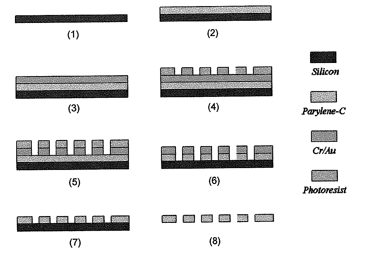
Filter Fabrication

[0067]As shown in FIG. 1, a parylene-C membrane filter was prepared according to the following processes.[0068]1. Prime silicon wafer as substrate.[0069]2. Coating of 10 μm parylene-C.[0070]3. Ebeam deposition of 10 nm Cr and 200 nm Au.[0071]4. Spin-coating of AZ1518 photoresist and lithography to form pattern.[0072]5. Wet-etching of metal layers using photoresist as mask.[0073]6. Reactive Ion Etching (RIE) of parylene-C to form slots (an array of 30,401 slots), using[0074]metal as mask.[0075]7. Strip off metal mask.[0076]8. Parylene-C membrane is peeled off from silicon substrate.

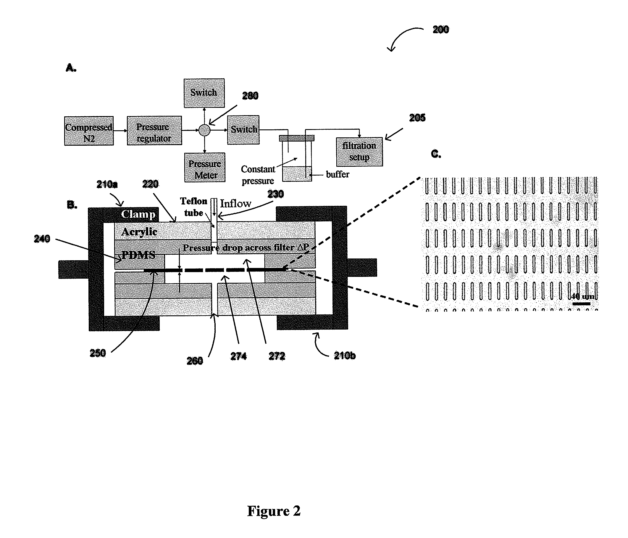
Constant Pressure Fluid Delivery System

[0077]Pressure from a nitrogen tank was reduced below 1 psi by a two-stage regulator (FIG. 2) and further down regulated accurately by adjusting a needle valve to 0.1-0.13 psi. A 15 ml conical tube containing the sample was connected as a reservoir. The filter was sandwiched between two thin pieces of p...

example 2

Use of Parylene-C Slot Microfilter-Based Enrichment of Blood CTCs

Capture Efficiency, Cell Viability and Enrichment:

[0078]PC3 and DU145 human prostate cancer cell lines were stained with Calcein-AM fluorescent dye, and 10 cells were spiked into 1 ml human blood obtained from healthy volunteers. After filtration, captured cells were co-stained with Propidium iodide (PI) on filter and counted under a fluorescent microscope (Zeiss Imager.Z1 microscope) with Axiovision software. Viable Calcein-AM-retaining cells were fluorescent green while dead cells were fluorescent red by PI.

Capture efficiency was calculated as:

Captureefficiency(%)=cancercells(green+red)onfiltercancercellsspikedintoblood×100

Cell viability was calculated as:

Cellviability(%)=greenfluorescentcellstotalcapturedcancercells(green+red)×100

Enrichment was determined by staining and counting the PBMCs remaining on filter with Acridine Orange and was calculated as:

Enrichment(fold)=(cancercells / PBMCs)onfilterpost-filtration(cance...

example 3

Quantitative PCR (QPCR) Telomerase Activity Assay

Telomeric Repeat Amplification Protocol (TRAP) Assay

[0083]Telomerase activity from cell extracts was analyzed using a previously described real-time PCR-based telomeric repeat amplification protocol (TRAP) (Xu T, Xu Y, Liao C P, Lau R, Goldkorn A. Reprogramming murine telomerase rapidly inhibits the growth of mouse cancer cells in vitro and in vivo. Mol Cancer Ther 2010; 9:438-49). The microfilter with captured cells was lysed in TRAPeze® 1× CHAPS Lysis Buffer (Millipore, 5 Temecula, Calif.), and 5 μl of cell lysate per reaction was added for each sample. For each reaction, DU145 cell lysates were used as standard controls in parallel.

[0084]QPCR telomerase activity assay was carried out as described below.

1. TS oligonucleotides (5′ AATCCGTCGAGCAGAGTT, 8 ng / μl) and 50 μM of each dNTPs are added to the cell lysate and incubated on a Bio-Rad MyiQ Thermocycler system for 30 min at 30° C. followed by inactivation of telomerase at 95° C. fo...


PUM

PropertyMeasurementUnit
pressureaaaaaaaaaa
thicknessaaaaaaaaaa
pressureaaaaaaaaaa

Abstract

The present invention provides a method for diagnosing cancer, predicting a disease outcome or response to therapy in a patient sample. The method involves isolating a circulating tumor cell (CTC), for example, a viable CTC, from a sample using a parylene microfilter device comprising a membrane filter having or consisting of a parylene substrate, which has an array of holes with a predetermined shape and size; and detecting and quantifying telomerase activity in blood circulating tumor cells. The invention further provides methods of using cells live-captured in various applications.

Description

CROSS-REFERENCES TO RELATED APPLICATIONS[0001]This application claims priority to U.S. Provisional Patent Application No. 61 / 180,021, filed May 20, 2009, which is herein incorporated by reference in its entirety for all purpose.STATEMENT AS TO RIGHTS TO INVENTIONS MADE UNDER FEDERALLY SPONSORED RESEARCH OR DEVELOPMENT[0002]The U.S. Government has certain rights in this invention pursuant to Grant No. K08 CA126983-01 awarded by the National Cancer Institute (NCI).BACKGROUND OF THE INVENTION[0003]Cancer is a major health concern worldwide, accounting for millions of deaths and untold pain and suffering each year. The biologic heterogeneity of this disease and the vast populations afflicted pose the pivotal questions of whom to treat and with which therapies, challenges that can only be addressed through the development of more accurate and informative biomarkers. Peripheral blood circulating tumor cells (CTCs) recently have been detected and shown to have prognostic and predictive val...

Claims


Application Information

Patent Timeline
Patent Type & Authority Applications(United States)
IPC IPC(8): C12Q1/68G01N33/574C12M3/06C12N5/09
CPCG01N33/5094C12Q1/6886Y10T436/25375C12N5/0693C12Q2600/118C12Q1/6806C12N2503/00C12Y207/07049G01N2001/4088G01N1/30G01N1/4077G01N33/57496G01N2333/9128
Inventor GOLDKORN, AMIRTAI, YU-CHONGXU, TONGLU, BO
Owner UNIV OF SOUTHERN CALIFORNIA
Why Eureka
Try Eureka