Bolometric detector for detecting electromagnetic waves

a detector and electromagnetic wave technology, applied in the field ofbolometric detectors, can solve the problems of significant adverse effect on performance, limited thermal isolation, and insufficient thermal isolation,

a detector and electromagnetic wave technology, applied in the field ofbolometric detectors, can solve the problems of significant adverse effect on performance, limited thermal isolation, and insufficient thermal isolation,

US20110057107A1Inactive Publication Date: 2011-03-10COMMISSARIAT A LENERGIE ATOMIQUE ET AUX ENERGIES ALTERNATIVES

Image

  • Bolometric detector for detecting electromagnetic waves
  • Bolometric detector for detecting electromagnetic waves
  • Bolometric detector for detecting electromagnetic waves

Examples


Embodiment Construction

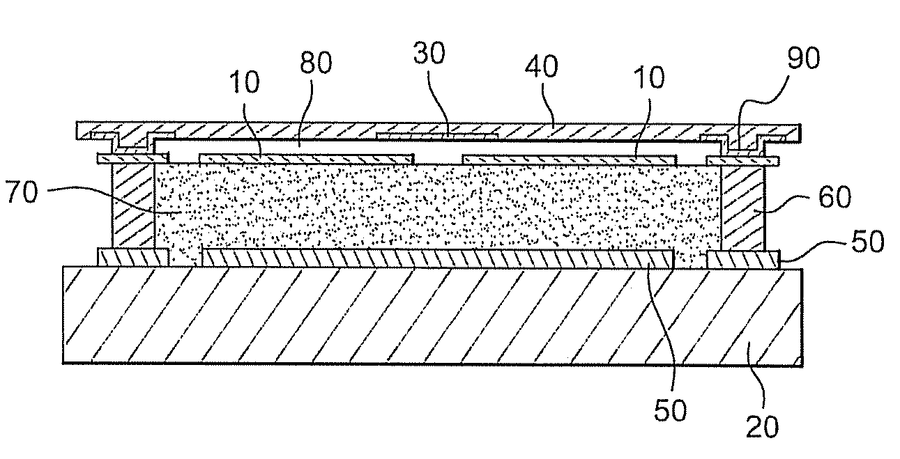
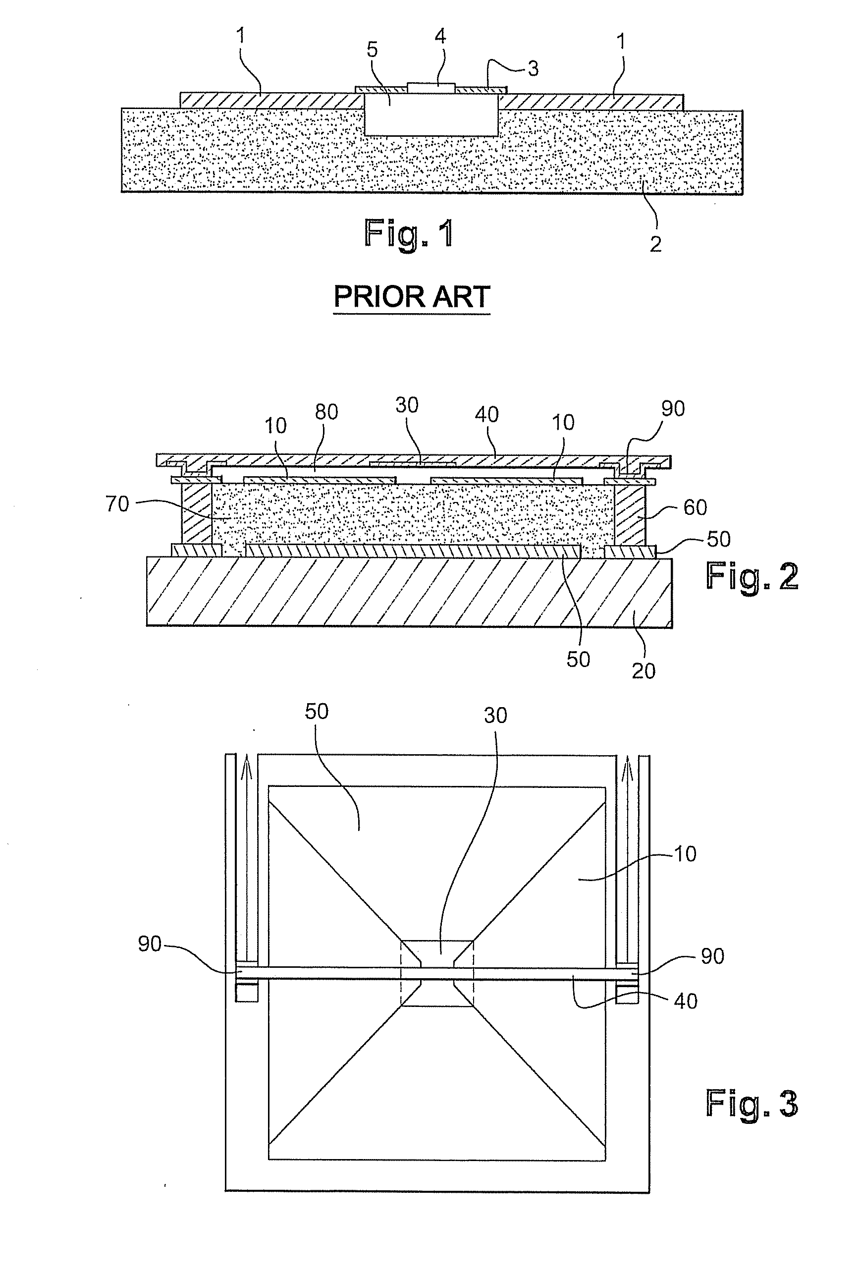
[0053]FIG. 2 shows a schematic cross-sectional view of an electromagnetic radiation detector in accordance with the invention. More especially, it shows one constituent pixel of such a detector.

[0054]This pixel is mounted on a substrate (20) which typically consists of a layer of silicon oxide SiO and a solid silicon Si substrate for example.

[0055]This substrate is also capable of being etched with a readout circuit that uses CMOS technology which is familiar to those skilled in the art.

[0056]A layer (50) designed to constitute a reflector is deposited on this substrate (20). This reflector comprises metallic layers having a low sheet resistance, for example layers made of materials selected from the group comprising Al, AlCu, AlSi, Ti. In a known manner, such a reflector is designed to reflect the wavelengths that are to be detected. This reflector is deposited on substrate (20) by sputtering, evaporation, Chemical Vapour Deposition (CVD) or any other technique for depositing thin-...


PUM


Abstract

A bolometric detector for detecting electromagnetic radiation comprising a receiving antenna intended for collecting electromagnetic radiation and thus ensuring electromagnetic coupling; a resistive load capacitively coupled to antenna and capable of converting the electromagnetic power collected into calorific power; and a thermometric element connected to resistive load and thermally isolated from a substrate that is capable of accommodating an electronic circuit that includes means of electrical excitation (stimulus) and pre-processing the electrical signals generated by said detector. The resistive load is suspended above receiving antenna by means of a single thermometric element which is itself electrically and mechanically linked to the substrate.

Description

FIELD OF THE INVENTION[0001]The invention relates to a bolometric detector, more especially one designed to detect electromagnetic waves from the infrared domain into the visible domain and even beyond, i.e. a detector that makes it possible to detect electromagnetic waves having wavelengths of several micrometres down to the submillimetric range (several hundred micrometres) or even the millimetric range.[0002]The detection of millimetric waves and, more especially, submillimetric waves has a certain number of attractions, especially on a scientific and technological level. Its known application areas include remote sensing, astrophysics in particular, but also imagers, radio astronomy from ground-based telescopes, biomedical imaging, etc.[0003]There are currently two known different physical principles that are used for detecting millimetric and submillimetric waves.[0004]The first of these involves detecting the electromagnetic waves by means of an antenna so as to create an elec...

Claims


Application Information

Patent Timeline
10 Mar 2011
Publication
US20110057107A1
IPC
G01J5/10
CPC
G01J5/08; G01J5/20; G01J5/0837
Inventors
AGNESE, PATRICK; ARNAUD, AGNES