Eureka AIR delivers breakthrough ideas for toughest innovation challenges, trusted by R&D personnel around the world.

Magnetic Detection of Small Entities

a small, magnetometer technology, applied in the field of magnetometer of small entities, can solve the problems of limited sensitivity and specificity, relatively labor-intensive and time-consuming microarray analysis, and not very suitable for diagnostics, and achieve the effect of reducing costs

Inactive Publication Date: 2011-03-10
STROMBERG MATTIAS +5
View PDF3 Cites 38 Cited by
  • Summary
  • Abstract
  • Description
  • Claims
  • Application Information

AI Technical Summary

Benefits of technology

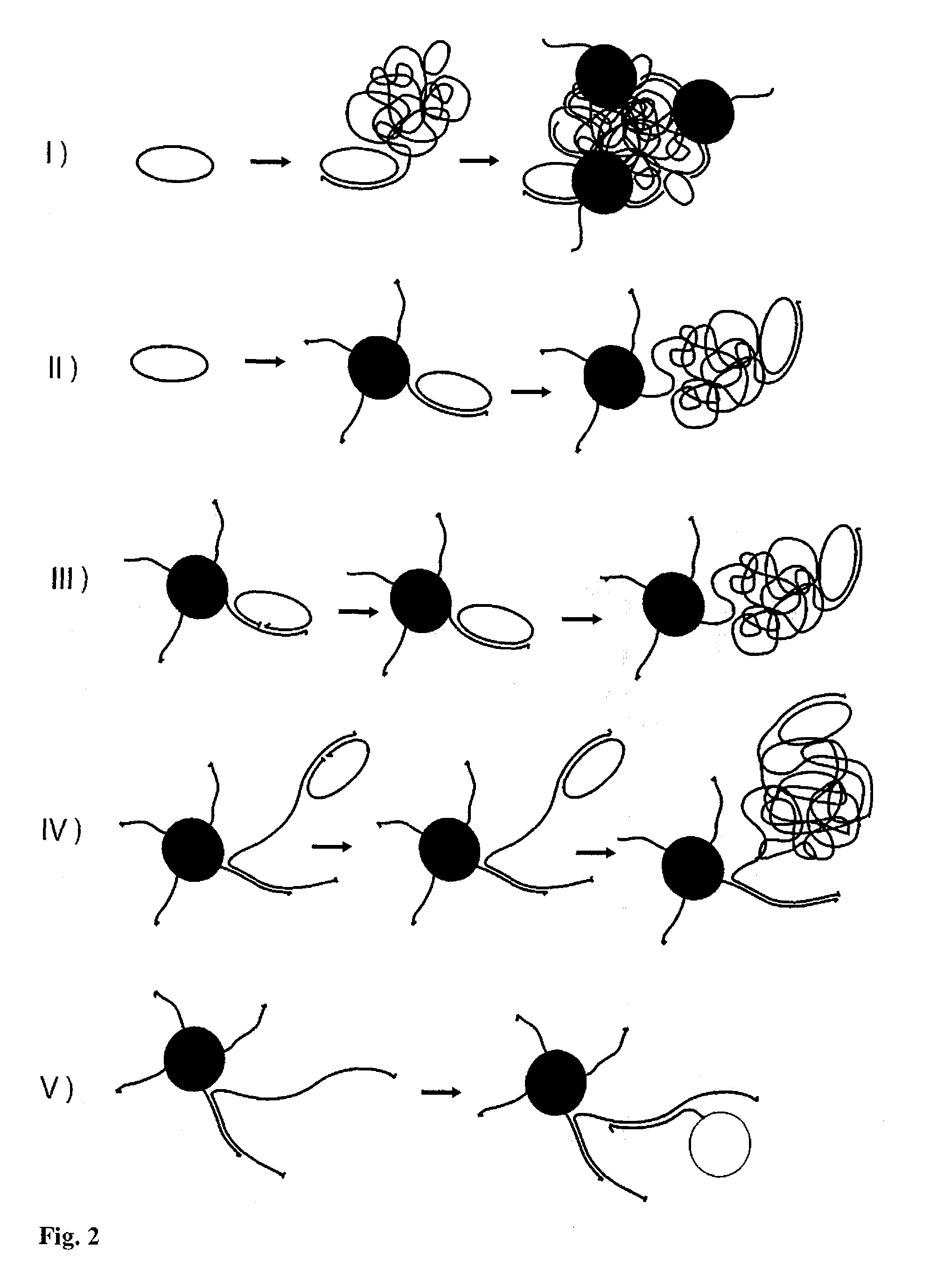
[0012]In a further embodiment, as mentioned above, the hydrodynamic volume of the target molecule may be directly increased by binding said target molecule to a passive particle via a secondary capturing probe.
[0013]The hydrodynamic volume of the entity after amplification should be increased to a size that makes it larger than the biological target to be detected by at least 10%, preferably 20%, more preferably 50%, even more preferably 100%, and most preferably 500%. The great increase in hydrodynamic volume affects the Brownian rotation and the dynamic magnetic properties (complex magnetization) of the magnetic nanoparticle bound to the volume-amplified entity in such a degree that quantification and / or detection step of a biological entity is enabled.
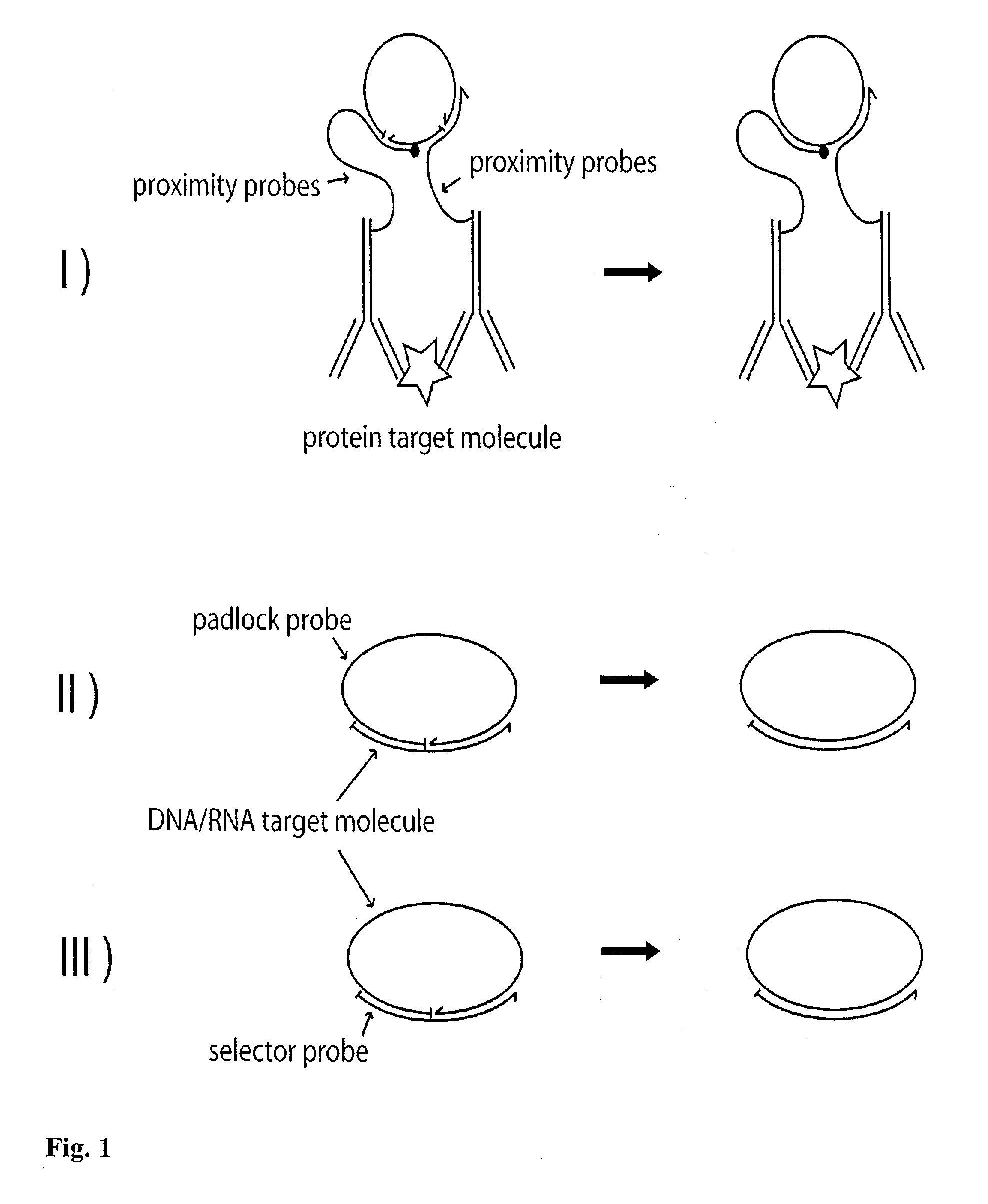
[0019]The detection method according to the present invention, for example implemented as a DNA sequence detection method relying on changes in magnetic properties in combination with the powerful padlock probe and RCA concepts, opens up potential possibilities to design high-sensitivity point-of-care and / or over-the-counter diagnostic tests at a much lower cost compared to already existing ones. It also opens up possibilities to design inexpensive high-sensitivity tests that can detect the presence (qualitative tests) and the concentration (quantitative tests) of microorganisms such as bacteria, viruses, and fungi, for bed-side and point-of-care applications and in veterinary medicine, in e.g. tests for biological contaminations or contents in food and pharmaceutical products, in water, air and environment, in military materials analysis, forensic analysis, etc. Examples of microorganisms that may be detected are, but not limited to, pneumococci, hemophilus, meningococci, tuberculosis and pertussis bacteria, the herpes viruses, candida and aspergillus fungi, plasmodium falciparum (causing malaria), E. coli, influenza, HIV as well as other RNA viruses. In this implementation of the technique, padlock probes are designed to target microbe-specific DNA / RNA sequences such that the padlock probes become circularized in a strictly target-dependent manner upon hybridization and ligation to the targeted DNA / RNA sequence. The formed DNA circles can then be replicated in a strictly circle-dependent RCA reaction, forming long tandem-repeated concatemer DNA molecules [Jarvius et al.]. The technique can be generalized to detection, quantification and analysis of any DNA or RNA sequence, e.g. genotyping of single-nucleotide polymorphisms, quantification of mRNA molecules or gene copy numbers.
[0021]The present invention further relates to a biosensor for use with the above mentioned method. Said biosensor is a mass-producible, low-cost and sensitive device producing the desired read-out signal, which in one embodiment is designed to be compatible with Fannin's toroidal technique [Fannin et al.]. Such a biosensor in combination with the above-mentioned method represents a fast, cheap and easy-handled way of measuring the complex magnetization of a liquid sample containing nanoparticles.

Problems solved by technology

Microarray analysis is relatively labour-some and time-consuming, and limited in sensitivity and specificity, and is therefore not very suitable for diagnostics.
Although the PCR scheme in principle provides unlimited sensitivity and quantitative dynamic range, the technique is considered too complicated for the diagnostic setting.
Although fluorescence detection of the RCA-products, the current state-of-the-art method for DNA sequence detection, has several advantages such as high selectivity and sensitivity, the equipment needed for this is expensive and rather difficult to miniaturize.

Method used


Image

  • Magnetic Detection of Small Entities
  • Magnetic Detection of Small Entities
  • Magnetic Detection of Small Entities

Examples


example 1

Detection of Single-Stranded DNA Using the RCA Technique

[0075]FIG. 4 shows an example of the invention implemented as single target DNA sequence detection step by step, using the RCA technique for amplification purposes. In upper left part of the figure, a solution containing single-stranded target-DNA molecules, indicated as curved black lines, is shown. Linear padlock probe molecules (curved white lines) designed to exactly match the target-DNA are added, which upon hybridization with the target-DNA molecules form circularized padlock probes. The ends of the padlock probe molecules are joined together by ligation. DNA polymerases are added and the RCA of the circularized padlock probes proceeds for a certain time (the RCA-time). After completion of RCA, the solution comprises random-coil single-stranded molecules having an approximate size of 1 μm (for an RCA-time of approximately 1 hr) [Strömberg et al. 2008a].

[0076]The presence of the RCA-coils is detected by addition of magneti...

example 2

Quantification of Single-Stranded DNA Using the RCA Technique (Amplification Before Binding to Magnetic Nanoparticles)

[0080]FIG. 5 (a) shows the imaginary part of the complex magnetization vs. frequency at 310 K for positive samples with various RCA-coil concentrations, ranging from 0 to 300 pM. The magnetic properties of the synthesised probe-tagged magnetic nanoparticles were found to be highly reproducible. The “0 M” curve corresponds to the negative control sample without RCA-coils [Strömberg et al. 2008a].

[0081]FIG. 5 (b) shows Δm″, defined as Δm″=m″(0)−m″(c), at the high frequency Brownian relaxation peak vs. RCA-coil concentration, c. Note the very clear correspondence between the high frequency peak m″ level and the RCA-product concentration. As the RCA-product concentration increases, more probe-tagged magnetic nanoparticles are incorporated into coils and therefore, the high frequency peak m″ level decreases [Strömberg et al. 2008a].

[0082]The high and low frequency Brownia...

example 3

Quantification of Single-Stranded DNA Using the RCA Technique (Amplification after Binding to Magnetic Nanoparticles)

[0086]In the above examples the hydrodynamic volume of the target molecule to be detected was enlarged before the binding reaction to functionalized magnetic nanoparticles exhibiting Brownian relaxation behavior. In another implementation of the present invention the hydrodynamic volume of the target molecule that binds to the magnetic nanoparticle is increased after such a binding reaction and prior to read-out.

[0087]To exemplify this, thiol modified oligonucleotide probes were immobilized on aminated 130 nm-sized magnetic nanoparticles using SPDP coupling chemistry [Strömberg et al. 2007b, Strömberg et al. 2008a] composed of a non-magnetic dextrane shell enclosing a magnetic aggregate consisting of 15 nm maghemite (γ-Fe2O3) nanoparticles, with each nanoparticle being in a single domain state. The types of probes and nanoparticles may however vary depending on desire...


PUM

PropertyMeasurementUnit
Fractionaaaaaaaaaa
Fractionaaaaaaaaaa
Fractionaaaaaaaaaa

Abstract

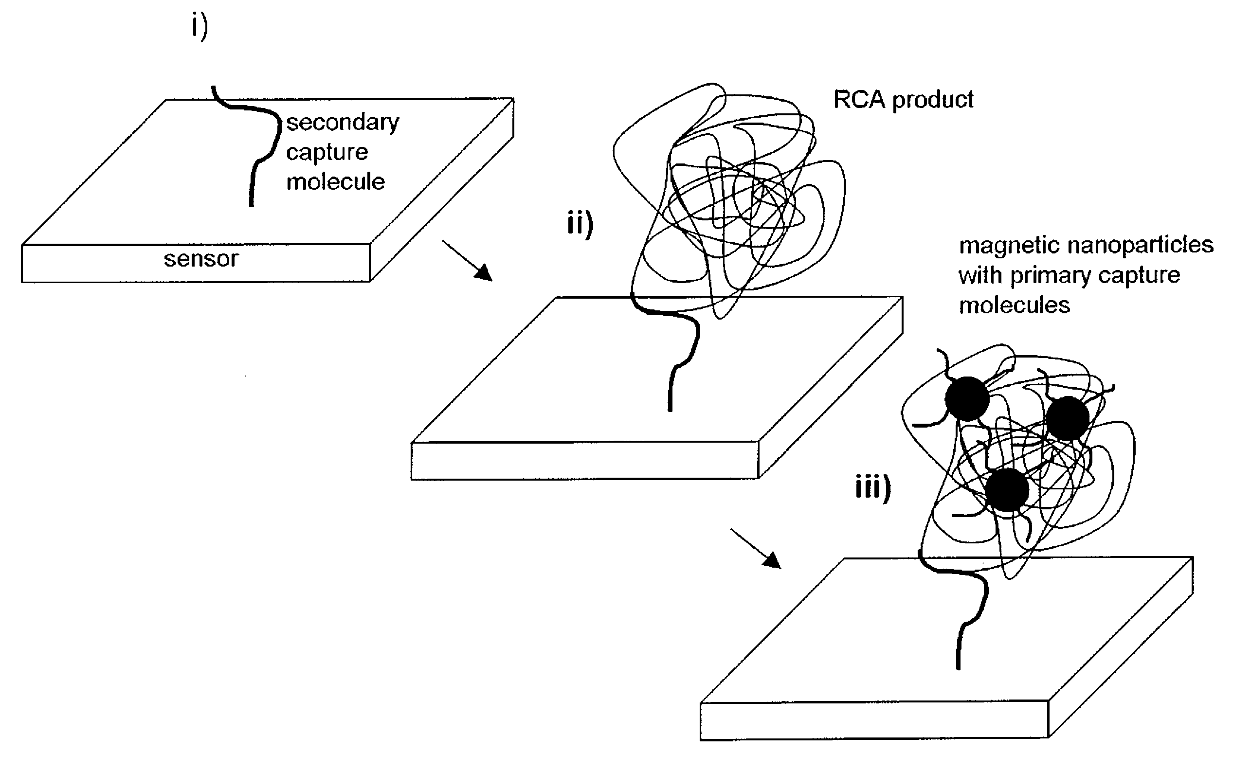
A novel detection or quantifying method for biological entities or molecules such as, but not limited to, DNA, microorganisms and pathogens, proteins and antibodies, that by themselves are target molecules or from which target molecules are extracted, comprises the steps of i) forming target molecule-dependent volume-amplified entities, ii) allowing magnetic nanoparticles to bind to said volume-amplified entities, and iii) measuring changes in dynamic magnetic response of the magnetic nanoparticles caused by the increase in hydrodynamic volume of said magnetic nanoparticles or measuring the magnetic field due to the magnetic nanoparticles as they bind to a sensor surface functionalized with a secondary capturing probe. Biosensors and kits are adapted to be used in such a method.

Description

FIELD OF THE INVENTION[0001]The present invention relates to a novel detection or quantifying method for biological entities or molecules such as, but not limited to, DNA, microorganisms and pathogens, proteins and antibodies, that by themselves are target molecules or from which target molecules are extracted. The methods comprise the steps of i) forming target molecule-dependent volume-amplified entities, ii) allowing magnetic nanoparticles to bind to said volume-amplified entities, and iii) measuring changes in dynamic magnetic response of the magnetic nanoparticles caused by the increase in hydrodynamic volume of said magnetic nanoparticles or measuring the magnetic field due to the magnetic nanoparticles as they bind to a sensor surface functionalized with a secondary capturing probe.[0002]The present invention further relates to biosensors and kits to be used in such a method.BACKGROUND OF THE INVENTION[0003]There is a need for novel simple assay formats for sensitive DNA sequ...

Claims


Application Information

Patent Timeline
IPC IPC(8): C12Q1/68C12M1/34B82Y15/00
CPCC12Q1/6844C12Q1/6851G01N33/542G01N2458/10C12Q1/6825C12Q2563/155C12Q2563/143C12Q2531/125C12Q2545/114
Inventor STROMBERG, MATTIASGORANSSON, JENNYGUNNARSSON, KLASNILSSON, MATSSVEDLINDH, PETERSTROMME, MARIA
Owner STROMBERG MATTIAS
Why Eureka
Eureka Blog
Learn More