Compound for organic electroluminescent device and organic electroluminescent device

a technology of electroluminescent devices and organic electroluminescent devices, which is applied in the direction of thermoelectric devices, anthracene dyes, other domestic articles, etc., can solve the problems of reducing the luminous efficiency, lowering the recombination, and failing to emit light at high efficiency, so as to secure the driving stability of the device, enhance the luminous efficiency of the device, and high efficiency

Active Publication Date: 2011-03-17
NIPPON STEEL CHEMICAL CO LTD
View PDF8 Cites 59 Cited by
  • Summary
  • Abstract
  • Description
  • Claims
  • Application Information

AI Technical Summary

Benefits of technology

[0016]In applications of organic EL devices to display devices such as flat panel displays, it is necessary to enhance the luminous efficiency of the device and, at the same time, to fully secure the driving stability of the device. Under the aforementioned circumstances, an object of this invention is to provide an organic EL device of high efficiency, good driving stability, and practical usefulness and to provide a compound suitable therefor.

Problems solved by technology

Europium complexes were also investigated in trials to utilize the excited triplet state, but they failed to emit light at high efficiency.
When CBP is used as a host material for tris(2-phenylpyridine)iridium complex (hereinafter referred to as Ir(ppy)3), a phosphorescent material emitting green light, the balance of electrical charges in the light-emitting layer is destroyed and excess holes flow out to the side of the cathode on account of the electron transport property being inferior to the hole transport property in the case of CBP and the result is lowering of the luminous efficiency due to lowering of the recombination probability in the light-emitting layer.
Furthermore, in this case, the recombination zone in the light-emitting layer is limited to a narrow space in the vicinity of the interface on the cathode side.
For example, the use of 4,4′-bis[N-(1-naphthyl)-N-phenylamino]biphenyl (hereinafter referred to as NPB), a material in widespread use for its good performance, high reliability, and long life, in the hole-transporting layer causes a problem that transfer of the triplet energy occurs from Ir(ppy)3 to NPB reflecting the relationship of the lowest triplet energy level between the two and the luminous efficiency becomes lower.
Furthermore, compounds like CBP and TAZ readily undergo crystallization and agglomeration with the resultant deterioration of the shape of thin film.
In addition, the Tg of such compounds is difficult to merely observe because of their high crystallinity.
The instability of the shape of thin film in the light-emitting layer exerts an adverse influence on the device such as shortening of the lifetime and lowering of the heat resistance.

Method used


Image

  • Compound for organic electroluminescent device and organic electroluminescent device
  • Compound for organic electroluminescent device and organic electroluminescent device
  • Compound for organic electroluminescent device and organic electroluminescent device

Examples


example 1

[0059]

[0060]In a nitrogen-blanketed 2,000-ml three-necked flask were placed 33.3 g (297.0 millimoles) of 1,2-cyclohexanedione and 86.0 g (594.7 millimoles) of phenylhydrazine hydrochloride, then 1,000 ml of ethanol was added, and the mixture was stirred. Thereafter, 3.0 g (30.6 millimoles) of concentrated sulfuric acid was added dropwise to the flask over 5 minutes and the resulting mixture was heated to 65° C. and stirred for 4 hours. The mixture was then cooled to room temperature, the purplish brown crystals formed were collected by filtration, and the crystals were reslurried twice in 500 ml of ethanol and then dried under reduced pressure to yield 80.0 g (280.5 millimoles, 96.3% yield) of a purplish brown powder.

[0061]Then, 72.0 g (261.5 millimoles) of the aforementioned purplish brown powder was placed in a 1,000-ml three-necked flask, then 720 g of acetic acid and 72.0 g of trifluoroacetic acid were added, and the mixture was stirred. The mixture was then heated to 100° C. an...

example 2

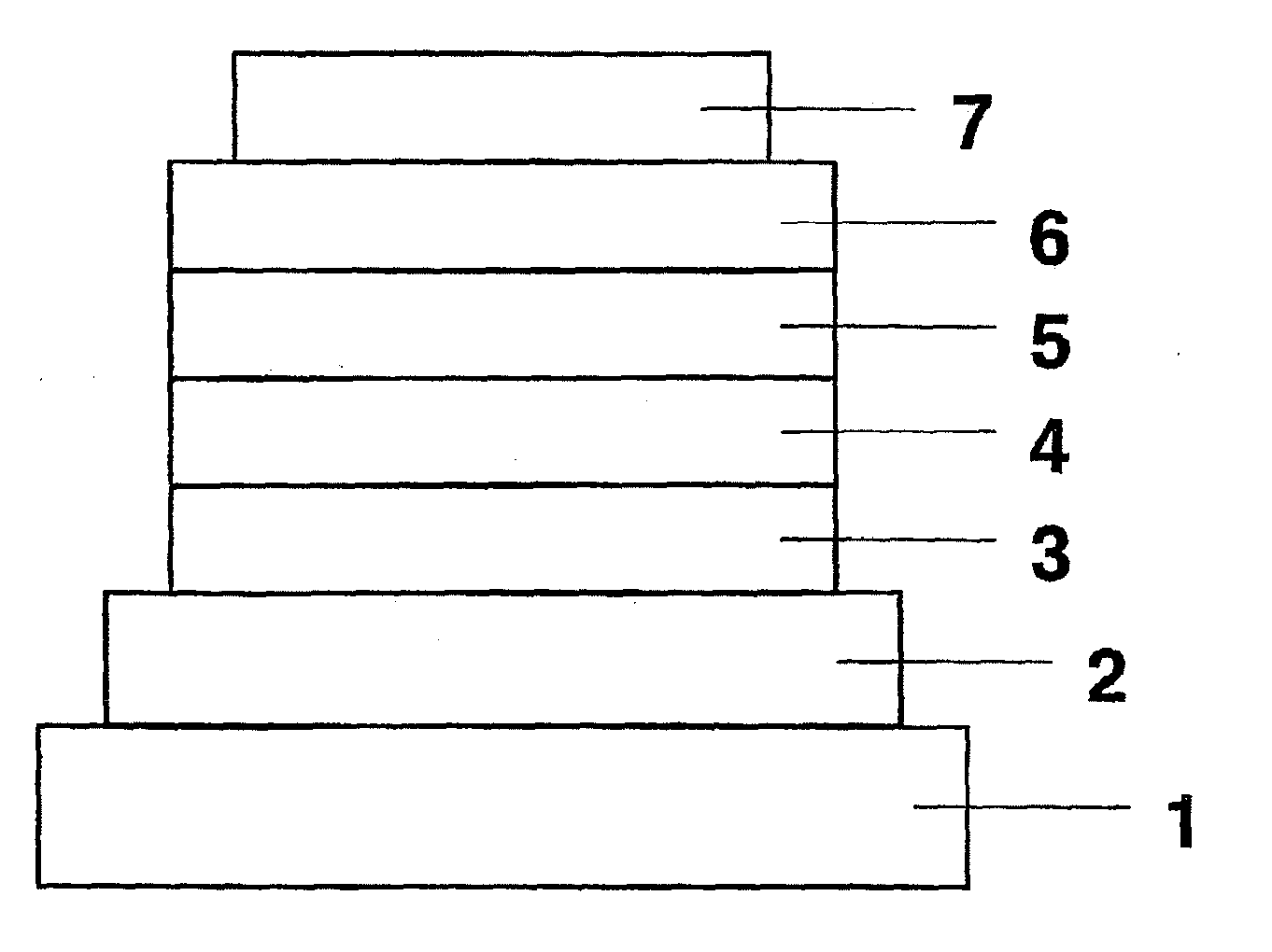
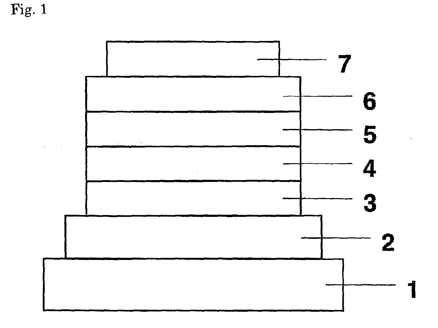
[0064]An organic EL device constituted as in FIG. 1 with addition of an electron-injecting layer was fabricated. Applying the vacuum deposition process at a degree of vacuum of 4.0×10⁻⁴ Pa, the constituent layers were deposited in thin film one upon another on a glass substrate on which a 150 nm-thick ITO anode had been formed. First, copper phthalocyanine (CuPC) was deposited on the ITO anode to a thickness of 20 nm as a hole-injecting layer. Then, NPB was deposited to a thickness of 40 nm as a hole-transporting layer. Next, Compound 3 as a host material and Ir(ppy)3 as a dopant were co-deposited from different evaporation sources on the hole-transporting layer to a thickness of 35 nm to form a light-emitting layer. At this point, the concentration of Ir(ppy)3 was 7.0 wt %. After this, Alq3 was deposited to a thickness of 40 nm as an electron-transporting layer. Further, lithium fluoride (LiF) was deposited on the electron-transporting layer to a thickness of 0.5 nm as an electron-...

example 3

[0066]An organic EL device was fabricated as in Example 2 with the exception of using Compound 2 as a host material in the light-emitting layer.


PUM

PropertyMeasurementUnit
thicknessaaaaaaaaaa
thicknessaaaaaaaaaa
thicknessaaaaaaaaaa

Abstract

Disclosed is an organic electroluminescent device (organic EL device) that is improved in the luminous efficiency, fully secured of the driving stability, and of a simple structure and also disclosed is a compound for organic EL device useful for the said device. The compound for organic EL device is, for example, an indolocarbazole derivative represented by the following general formula (3). The organic EL device comprises a light-emitting layer disposed between an anode and a cathode piled one upon another on a substrate and the said light-emitting layer comprises a phosphorescent dopant and the aforementioned indolocarbazole derivative as a host material. In general formula (3), L is an aromatic heterocyclic group of a fused-ring structure with a valence of (n+1), Ar1 to Ar3 each is an alkyl group, an aralkyl group, or a substituted or unsubstituted aromatic hydrocarbon or aromatic heterocyclic group, and n is an integer of 0-5.

Description

FIELD OF TECHNOLOGY[0001]This invention relates to a novel compound for organic electroluminescent device and to an organic electroluminescent device (hereinafter referred to as organic EL device) using the said novel compound.BACKGROUND TECHNOLOGY[0002]An organic electroluminescent device in the simplest structure is generally constituted of a light-emitting layer and a pair of counter electrodes sandwiching the said light-emitting layer. The device functions by utilizing the following phenomenon; upon application of an electrical field between the electrodes, electrons are injected from the cathode and holes are injected from the anode and they recombine in the light-emitting layer with emission of light.[0003]In recent years, organic thin films have been used in the development of organic EL devices. In particular, in order to enhance the luminous efficiency, the kind of electrodes has been optimized for the purpose of improving the efficiency of injecting carriers from the elect...

Claims


Application Information

Patent Timeline
Patent Type & Authority Applications(United States)
IPC IPC(8): H01L51/54C07D487/04C07D471/04C07D471/14
CPCC07D487/04Y10S428/917C09K2211/1007C09K2211/1011C09K2211/1029C09K2211/1044C09K2211/185H01L51/0072H01L51/5016H05B33/20C09B47/00C09B57/00C09B57/10C09B67/0033C09K11/06H10K85/6572H10K50/11H10K2101/10H10K2102/00
Inventor KAI, TAKAHIROKOMORI, MASAKIYAMAMOTO, TOSHIHIRO
Owner NIPPON STEEL CHEMICAL CO LTD
Why Eureka
Try Eureka