Radiation-selective absorber coating and absorber tube with said radiation-selective absorber coating

a radiation-selective absorber and absorber tube technology, applied in the field of radiation-selective absorber coatings, can solve the problems of reducing the absorption efficiency of the cermet layer and the reflectivity of the reflective layer that reflects infrared radiation, destroying and lumping the layer system, etc., and achieve good adhesion

Active Publication Date: 2011-04-21
RIOGLASS SOLAR HLDG SA
View PDF26 Cites 15 Cited by
  • Summary
  • Abstract
  • Description
  • Claims
  • Application Information

AI Technical Summary

Benefits of technology

[0015]In this context, it is an object of the invention to provide an absorber coating whose...

Problems solved by technology

However contrary to this the durability of the layer system of the absorber coating decreases with increasing operating temperature because of ageing and/or diffusion processes, as a result of which, for example, the absorptance of the cermet layer and the reflectivity of the reflective layer that reflects in...

Method used


Image

  • Radiation-selective absorber coating and absorber tube with said radiation-selective absorber coating
  • Radiation-selective absorber coating and absorber tube with said radiation-selective absorber coating
  • Radiation-selective absorber coating and absorber tube with said radiation-selective absorber coating

Examples


Embodiment Construction

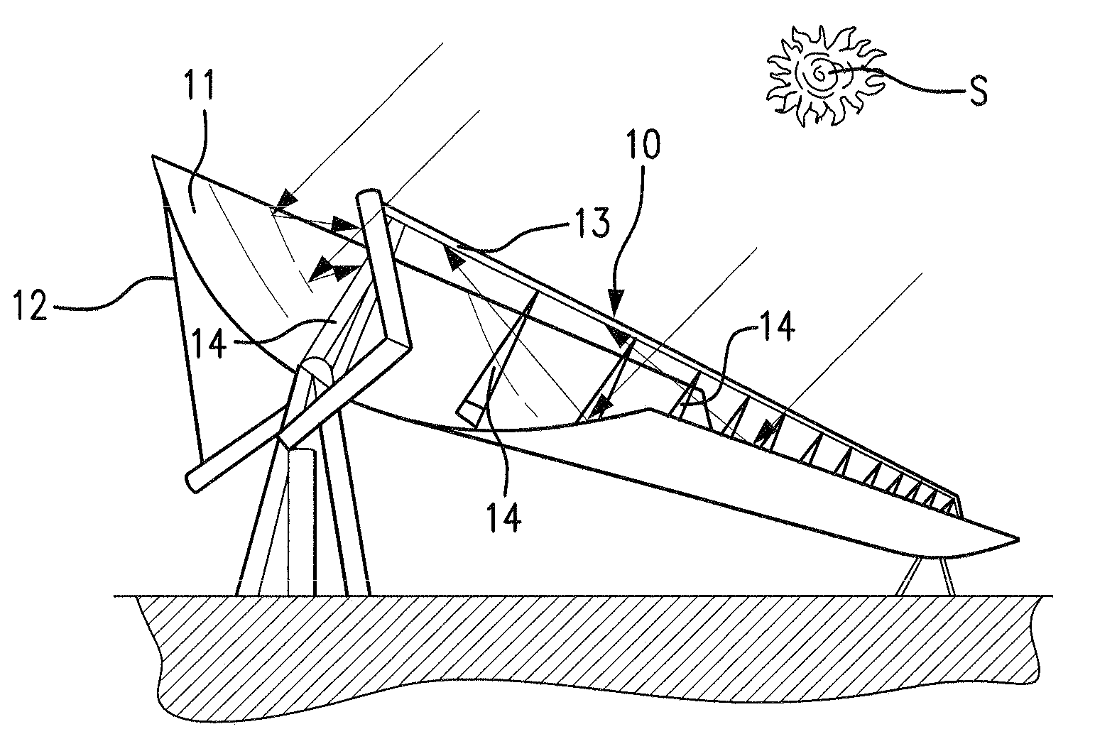
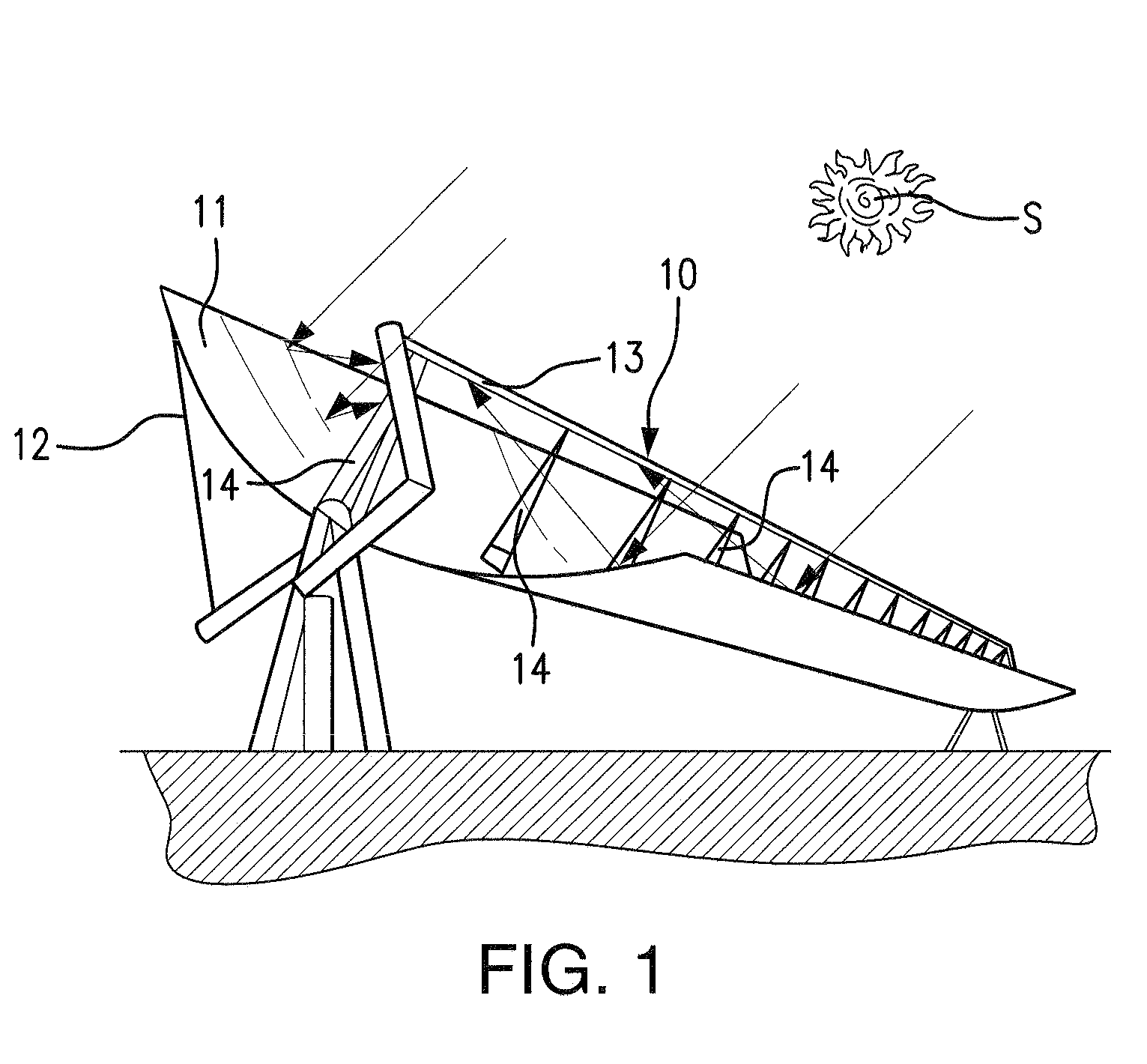
[0052]FIG. 1 illustrates a parabolic trough collector 10, which has an elongated parabolic reflector 11 with a parabolic profile. The parabolic reflector 11 is supported by a support structure 12. Along the focal line of the parabolic reflector 11 there extends an absorber tube 13, which is fixed to supports 14 connected to the parabolic trough collector. The parabolic reflector 11 forms a unit with the supports 14 and the absorber tube 13. This unit is pivoted about the axis of the absorber tube 13 and thereby uniaxially tracks the position of the sun S. The parallel solar radiation incident from the sun S is focused by the parabolic reflector 11 onto the absorber tube 13. A heat carrier medium, in particular water, flows through the absorber tube 13, the latter being heated by the solar radiation absorbed. At the outlet end of the absorber tube, the heat transfer medium can be withdrawn and fed to an energy consumer or converter.

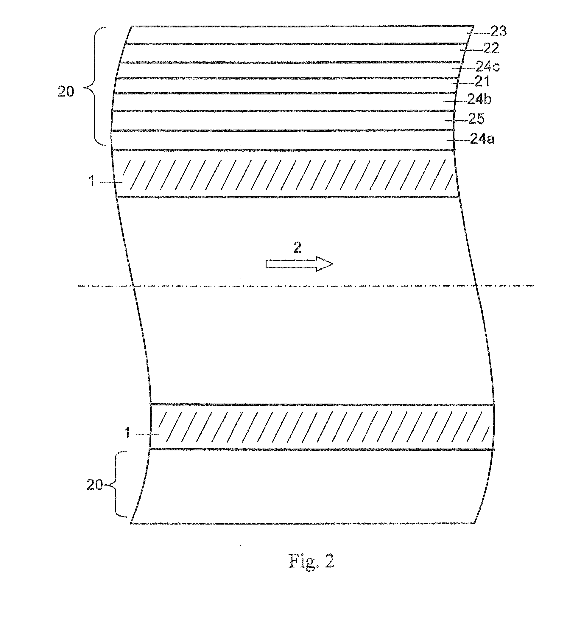
[0053]FIG. 2 schematically illustrates a section thr...


PUM

PropertyMeasurementUnit
Fractionaaaaaaaaaa
Fractionaaaaaaaaaa
Thicknessaaaaaaaaaa

Abstract

The radiation-selective absorber coating for absorber tubes of parabolic trough collectors includes two or more barrier layers (24a, 24b); an infrared reflective layer (21) on the barrier layers (24a, 24b); at least one cermet absorption layer (22) above the infrared reflective layer (21) and an antireflection layer (23) above the at least one cermet absorption layer (22). The two or more barrier layers (24a, 24b) include a first barrier layer (24a) of thermally produced oxide and a second barrier layer (24b) arranged above it. The second barrier layer (24b) is a cermet material including at least one oxide compound and at least one metal. The oxide compound is aluminium oxide, silicon oxide, nickel oxide and/or chromium oxide. The metal is molybdenum, nickel, tungsten and/or vanadium. The invention also includes an absorber tube with the absorber coating on it.

Description

CROSS-REFERENCE[0001]The subject matter described and claimed herein below is also described in German Patent Application No. 10 2009 049 471.5, filed on Oct. 15, 2009 in Germany. This German Patent Application provides the basis for a claim of priority of invention for the invention described and claimed herein below under 35 U.S.C. 119 (a)-(d).BACKGROUND OF THE INVENTION[0002]1. The Field of the Invention[0003]The invention relates to a radiation-selective absorber coating comprising at least two barrier layers, an infrared reflective layer applied on the barrier layers, at least one absorption layer arranged above the infrared reflective layer and an antireflection layer arranged above the at least one absorption layer, wherein a first barrier layer consists of a thermally produced oxide. The invention also relates to an absorber tube having a radiation-selective coating of this type, and to a method of operating a parabolic trough collector containing absorber tubes of this type...

Claims


Application Information

Patent Timeline
IPC IPC(8): F24J2/48B32B15/04F24S20/20
CPCF24J2/07Y10T428/1266Y02E10/41F24J2/487Y10T428/265F24J2/4652F24S70/25F24S70/30F24S20/20Y10T428/31678F24S70/225Y02E10/40
Inventor KUCKELKORN, THOMASSILMY, KAMELDREYER, SEBASTIAN
Owner RIOGLASS SOLAR HLDG SA
Why Eureka
Try Eureka