Turbine housing for an exhaust gas turbocharger of an internal combustion engine

a technology of internal combustion engine and turbine housing, which is applied in the direction of machines/engines, liquid fuel engines, forging/pressing/hammering apparatuses, etc., can solve the problems of low efficiency, high flow loss, and pressure increase at the exhaust gas outlet of the turbine housing or of the exhaust gas turbocharger, so as to achieve optimal flow influencing, improve the usability of different types of internal combustion engines, and ensure gas tightness. the effect of reliable guaran

Inactive Publication Date: 2011-04-21
DAIMLER AG
View PDF12 Cites 9 Cited by
  • Summary
  • Abstract
  • Description
  • Claims
  • Application Information

AI Technical Summary

Benefits of technology

[0011]It has thereby been found to be advantageous in a further embodiment if the vane structure of the housing module is arranged between the further spiral channel and the turbine wheel receiving space. In other words, the housing module and the partial housing are adapted to each other in such a manner that the louver is arranged in the region of an exhaust gas outlet of the spiral channel, whereby an optimal flow influencing is made possible. It can thereby be provided that the housing module forms a nozzle of the spiral channel.
[0012]It is another advantage that the housing module for sealing the spiral channels with regard to each other comprises a sealing surface, which cooperates with a sealing surface of an intermediate wall of the partial housing arranged between the spiral channels. A complete gas tightness of the spiral channels with regard to each other can be ensured hereby, so that the exhaust gas flows through the spiral channels without thermodynamically damaging leakages.
[0013]In a further advantageous arrangement of the invention, that the sealing surface of the housing module is pressed to the sealing surface of the intermediate wall and / or that a sealing element, in particular a piston ring and / or a thermal compensation ring, is arranged between the sealing surfaces of the housing module and the intermediate wall. Hereby, temperature and geometry fluctuations occurring during the operation of the associated turbocharger can be compensated for in an advantageous manner and the desired gas tightness can be ensured reliably. This is for example of advantage with housings which are differently formed or housing modules of different materials whereby thermally induced movements between the individual components can be caused by different material pairings.
[0014]Preferably, a first heat expansion coefficient of a material of the housing module is larger than a second heat expansion coefficient of a second material of the partial housing and / or of the intermediate wall so that an expansion of the housing module with regard to the partial housing and / or the intermediate wall is obtained in a defined manner, which can effect a sealing. As the material of the housing module, an austenitic alloy based on Ni is particularly suitable and as the material of the partial housing and / or of the intermediate wall a usual sphere-graphitic gray cast iron may be chosen.
[0015]In an advantageous embodiment of the invention a further vane structure which is arranged between a spiral channel and the receiving space and axially adjustable with regard to a rotational axis of the turbine wheel and / or a flow element with a given inner contour is arranged in the region of the exhaust gas outlet of the turbine housing. This permits controlling the exhaust gas flow to the turbine wheel, so that the flexibility of the turbine housing according to the invention and its usability for different types of internal combustion engines can be increased further. By means of the adjustable vane structure, a so-called turbobrake functionality can for example be provided. The area of the exhaust gas outlet is particularly suitable because it offers the needed installation space.
[0016]A further aspect of the invention relates to an exhaust gas turbocharger for an internal combustion engine, wherein a simple and cost-efficient adaptability to different types of internal combustion engines is provided for according to the invention in that the turbine housing comprises at least one partial housing comprising the at least one spiral channel and a housing module fastened to the partial housing, which has a vane structure arranged upstream of the receiving space and an attachment surface, at which the bearing section is supported at least indirectly. The exhaust gas turbocharger has thus a modular construction, whereby a flexible construction kit is provided, where the different requirements of different internal combustion engines can be considered in a particularly simple manner by a suitable choice of a respective housing module provided with different louvers. Furthermore, a significant efficiency increase of the associated internal combustion engine is obtained compared to the state of the art due to the optimal adaptability. Further advantages can already be taken from the previous descriptions of the turbine housing according to the invention.

Problems solved by technology

The required high turbine performances of exhaust gas turbochargers are in other words realized by an increase of the back pressure capability or by the reduction of the flow volume reserve of the exhaust gas turbochargers in cooperation with the respective internal combustion engine, which however leads to low efficiencies.
These exhaust gas after-treatment systems lead to a pressure increase at an exhaust gas outlet of the turbine housing or of the exhaust gas turbocharger.
However, the spiral channels of these turbine housings have also reached spiral sizes in the meantime which result in very high flow losses by means of wall frictions and due to the small dimensions.
Additionally, certain problems exist with regard to the exhaust gas recirculation capability in connection with the necessary combustion air of the internal combustion engine in particular in the lower to the medium speed range.
A particular problem resides in the fact that the known turbine housings or the exhaust gas turbochargers provided with these housings have to be adapted in a constructively elaborate manner, in order to be able to be utilized with satisfactory efficiencies for different types of internal combustion engines.
Hereby, large production, storage holding and part costs are encountered.

Method used


Image

  • Turbine housing for an exhaust gas turbocharger of an internal combustion engine
  • Turbine housing for an exhaust gas turbocharger of an internal combustion engine
  • Turbine housing for an exhaust gas turbocharger of an internal combustion engine

Examples


first embodiment

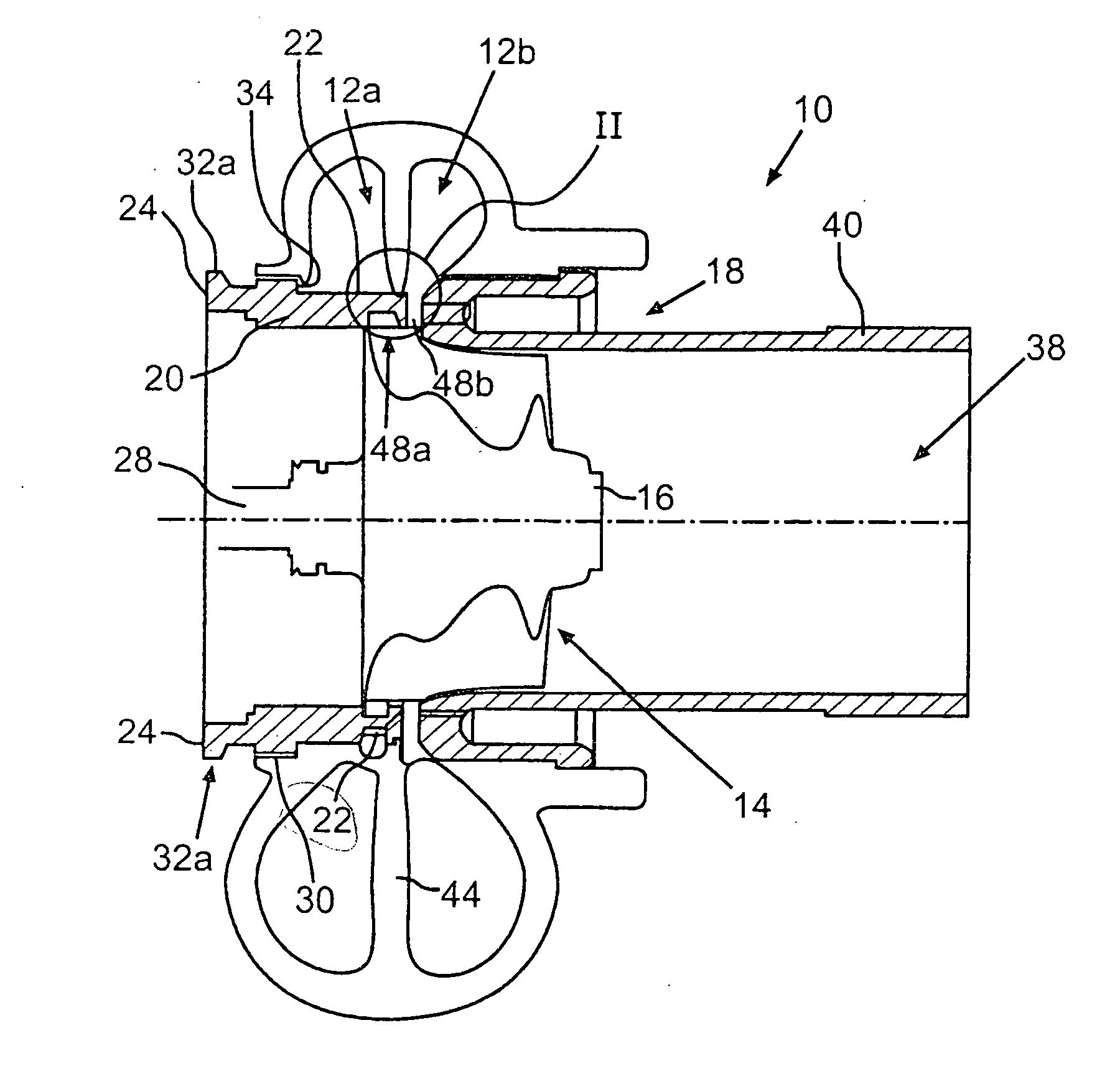
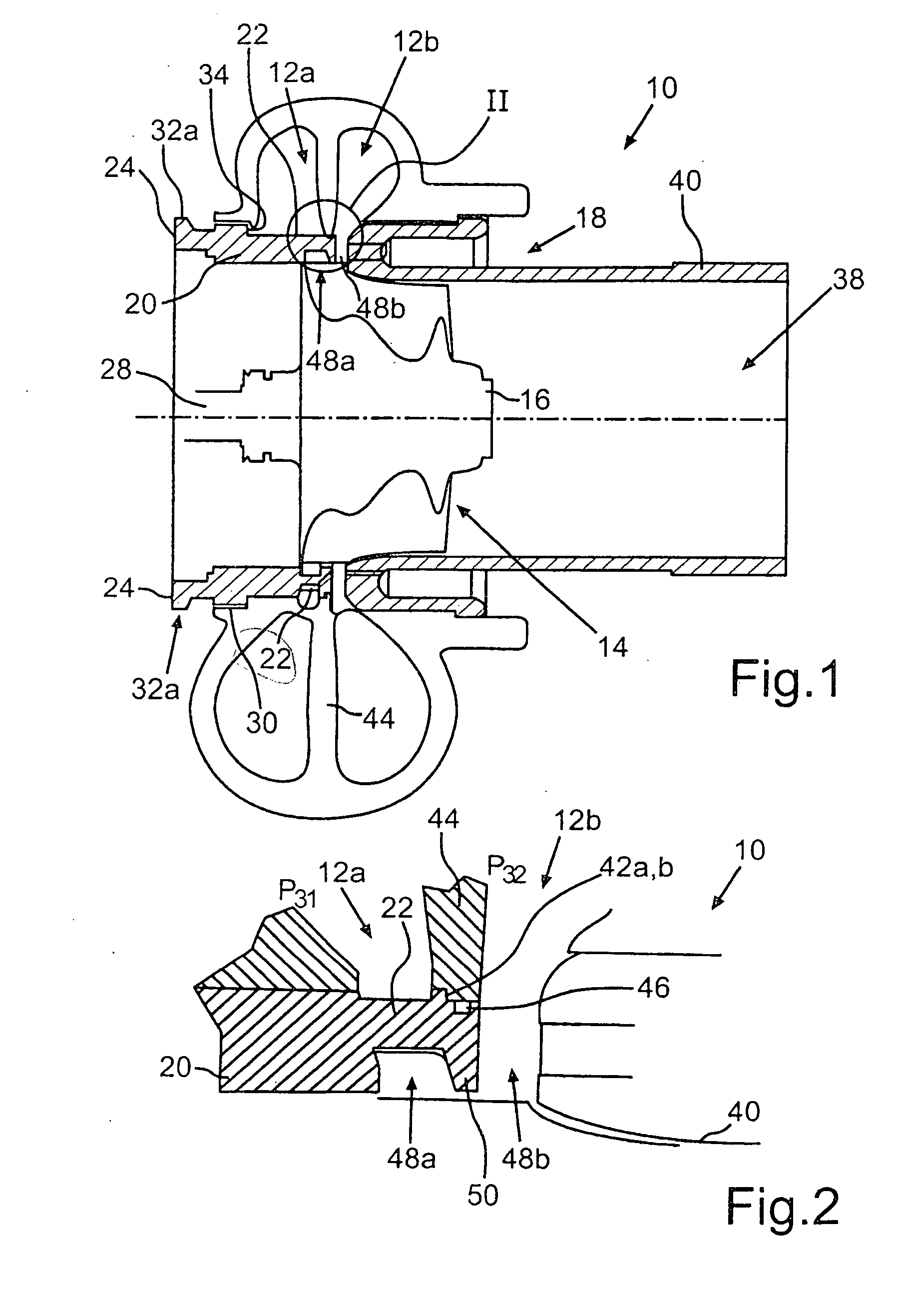
[0029]FIG. 1 shows a schematic lateral sectional view of a turbine housing 10 of an exhaust gas turbocharger (not shown) according to a The turbine housing 10 is in the form of a double-flow radial turbine and comprises two spiral channels 12a, 12b, which can be coupled to different exhaust gas flows of an exhaust gas tract of an associated internal combustion engine and through which exhaust gas flows can be conducted independently of each other. A receiving space 14 is disposed downstream of the two spiral channels 12a, 12b, in which space is arranged a turbine wheel 16, which can be acted upon by exhaust gas of the internal combustion engine supplied thereto via the spiral channels 12a, 12b. For adapting the turbine housing 10 or the exhaust gas turbocharger provided therewith in a simple and cost-efficient manner to different types to internal combustion engines, the turbine housing 10 has a partial housing 18 comprising the spiral channels 12a, 12b and a housing module 20 fast...

second embodiment

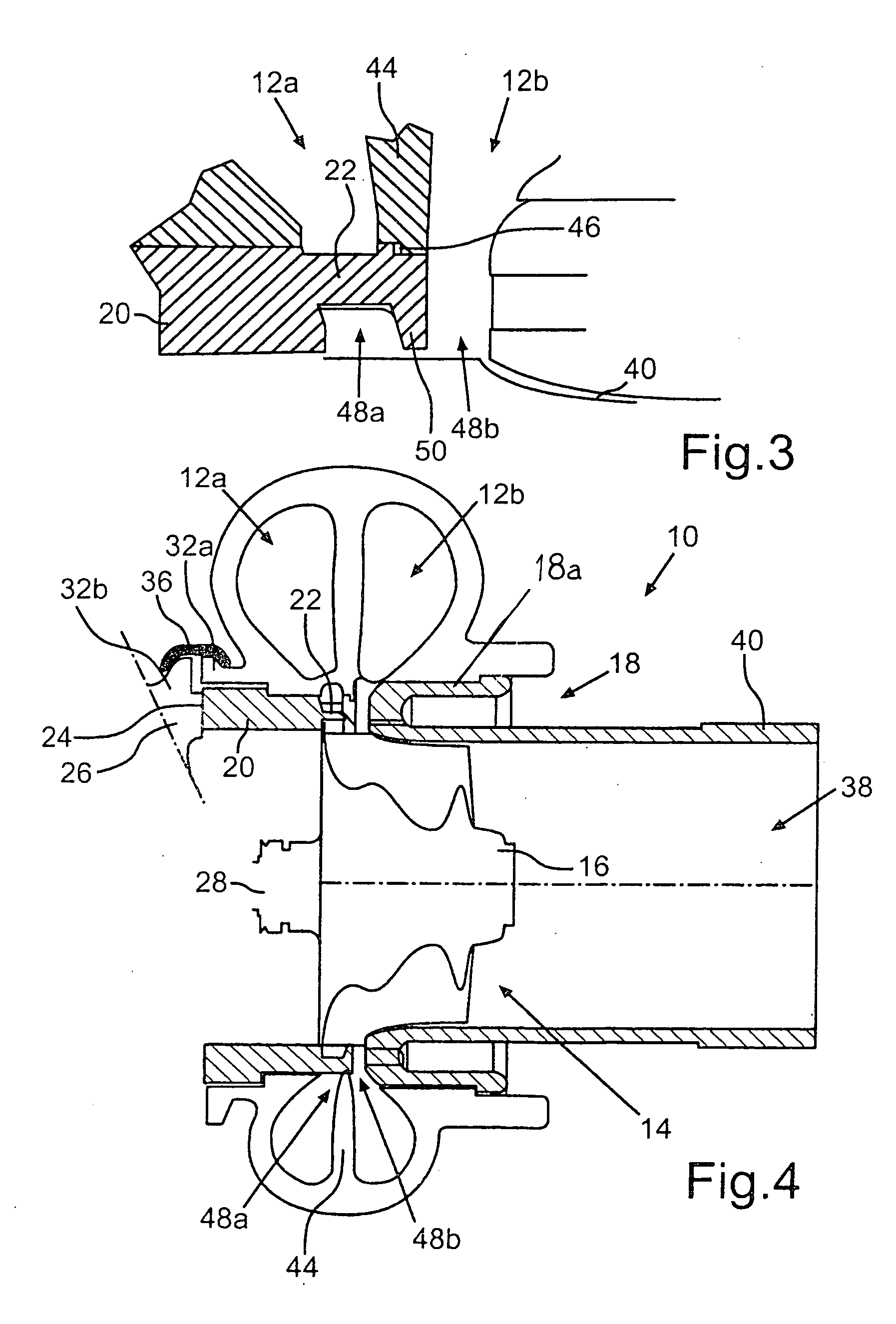
[0031]FIG. 3 is a schematic sectional view of the partial housing module 20 and shows partially in sections part of the housing module 20 of the turbine housing 10 according to a In contrast to the turbine housing 10 shown in FIG. 2, the sealing element 46 presently arranged between the sealing surfaces 42a, 42b of the housing module 20 and the intermediate wall 44 is formed as a thermal compensation ring. As relatively large component temperature fluctuations can occur during the operation of the internal combustion engine, the sealing element 46 in the form of a compensation ring provides for an operation-safe balance of the thermal movements occurring in dependence on the geometric and design configuration at the material side between the intermediate wall 44 and the housing module 20. The sealing surface 42a of the housing module 20 is again additionally pressed toward the sealing surface 42b of the intermediate wall 44, so that a defined pretension in the cold state and thus a...


PUM

PropertyMeasurementUnit
heat expansion coefficientaaaaaaaaaa
pressureaaaaaaaaaa
pressure dropaaaaaaaaaa

Abstract

In a turbine housing for an exhaust gas turbocharger of an internal combustion engine with at least one spiral channel, which can be coupled into an exhaust gas flow of an exhaust tract of the internal combustion engine, and a receiving space for a turbine wheel which is disposed downstream of the at least one spiral channel and can be acted upon by the exhaust gas of the internal combustion engine passing through the at least one spiral channel of the turbine housing, there is at least one partial housing including the at least one spiral channel, and a housing module which is fastened to the partial housing and has a vane structure disposed upstream of the receiving space which also includes an attachment surface for a bearing section of the exhaust gas turbocharger. The invention also resides in an exhaust gas turbocharger with such a turbine housing as well as to a method for producing such a turbine housing.

Description

[0001]This is a Continuation-In-Part Application of pending international patent application PCT / EP2009 / 004431 filed Jun. 19, 2009 and claiming the priority of German patent application 10 2008 032 492.2 filed Jul. 5, 2008.BACKGROUND OF THE INVENTION[0002]The invention relates to a turbine housing for an exhaust gas turbocharger of an internal combustion engine including at least one spiral channel structure, and to an exhaust gas turbocharger including such a turbine housing as well as to a method for producing a turbine housing for an exhaust gas turbocharger.[0003]Due to the continuous tightening of the emission limit values, for example the NOx and soot emission values, the demands on exhaust gas turbochargers or charged internal combustion engines also increase. Thus, for example, there are growing demands with regard to the charge pressure over the medium to high load operations of the internal combustion engine, as a result of which exhaust gas turbochargers have to be decrea...

Claims


Application Information

Patent Timeline
Patent Type & Authority Applications(United States)
IPC IPC(8): F04D29/44F04D29/60F04D29/54B23P15/04
CPCF01D17/16F02C6/12F05D2220/40Y10T29/4932F05D2240/14F05D2230/61F05D2300/50212F05D2230/50
Inventor KRATSCHMER, STEPHANLOFFLER, PAULMULLER, MARKUSSUMSER, SIEGFRIED
Owner DAIMLER AG
Why Eureka
Try Eureka