Ozone Generator Systems, Methods and Apparatus

a technology of ozone generator and ozone generator, which is applied in the direction of water/sewage treatment by oxidation, separation process, and treatment involving filtration, etc. it can solve the problems of chronic corrosion of materials by high concentrations of ozone, bacterial and viral contamination of such foodstuffs, and so as to increase the amount of ozone and the effect of enhancing ozone production

Active Publication Date: 2011-05-19
CUSTOM MOLDED PROD
View PDF15 Cites 9 Cited by
  • Summary
  • Abstract
  • Description
  • Claims
  • Application Information

AI Technical Summary

Benefits of technology

[0070]Alternatively, the slabs used in the fabrication of the ozone generator of the present invention can be fabricated as identical wafers or slabs first, and then shaped using cutting tools such as diamond saws or grinders to form the notches or voids of the top and bottom slabs, and the central opening of the middle slab. Of course, an advantage of this method is that the manufacture and assembly of the slabs in two the basic ozone generator can easily be mechanized and assembled using robotic manufacturing equipment without the need for detailed quality-control procedures involving the intermediate steps of manufacture.
[0071]The electrodes used in the ozone generators of the present invention should be placed on opposite, preferably flat, sides of the assembled device, in each case substantially directly over the location of the discharge chamber. It is particularly effective to place the electrodes in a generally centrally located position with respect to the outline of the discharge chamber underneath. If the electrodes are thus positioned, the resulting coronal discharge when a high-voltage electrical source is connected to the electrodes will be more effective, thereby maximizing the amount of ozone that can be generated within the discharge chamber.
[0072]In certain embodiments of the invention, two or more Corrosion Resistant Ozone Generators in accordance with the present invention can be utilized together if larger volumes of water are to be treated, for example for larger pools, large laundry purposes, or agricultural applications. In one particularly useful embodiment, accordingly, two or more Corrosion Resistant Ozone Generator assemblies or two or more Corrosion Resistant Ozone Generators, may be “teamed” together in a serial or parallel or a combination of serial and parallel configuration to provide enhanced ozone production to applications in which the amount of ozone required to be produced is higher. Examples of such embodiments are provided in the Examples herein.

Problems solved by technology

As a result of the use of certain sources of water or fertilizers there have been reports of bacterial and viral contamination of such foodstuffs.
However, the generation of ozone creates certain problems particular to the process.
Therefore, for example, high concentrations of ozone can be chronically corrosive to materials, such as (without exception) metals, alloys, and rubber.
Further corrosion may be caused when air rather than pure oxygen is used as the source of diatomic molecular oxygen and nitrogen containing salts and acids can be formed.
All of this material can thereby shortening the useful life of an ozone generator and other related equipment, conduits, hoses, housings, contacts, fittings, pipes, wires and the like located in close proximity to the ozone generator.
This nitric acid also shortens the life of the entire ozone generator system.
Such air-using ozone generators have the disadvantage, as discussed above, that when the ozone generator is discharged continuously, corrosive or contaminating nitrogenous compounds such as ammonium nitrate or nitric acid may form or be deposited on the electrodes or other portions of the ozone generator as a result of their reaction with nitrogen in air, resulting in corrosion or otherwise interfering with the function of the device.
More particularly, because untreated air often has a humidity percentage higher than that of artificially-produced dry air, large amounts of nitrogen oxides can be produced when ozone is generated by discharge.
However, these generators do have certain drawbacks that other ozone generators disclosed elsewhere herein do not have.
For example, the UV light lamp is relatively bulky, can burn out (often requiring system disassembly and lamp replacement) and systems containing such lamps are relatively inefficient in producing the desired amounts of ozone.

Method used


Image

  • Ozone Generator Systems, Methods and Apparatus
  • Ozone Generator Systems, Methods and Apparatus
  • Ozone Generator Systems, Methods and Apparatus

Examples


example 1

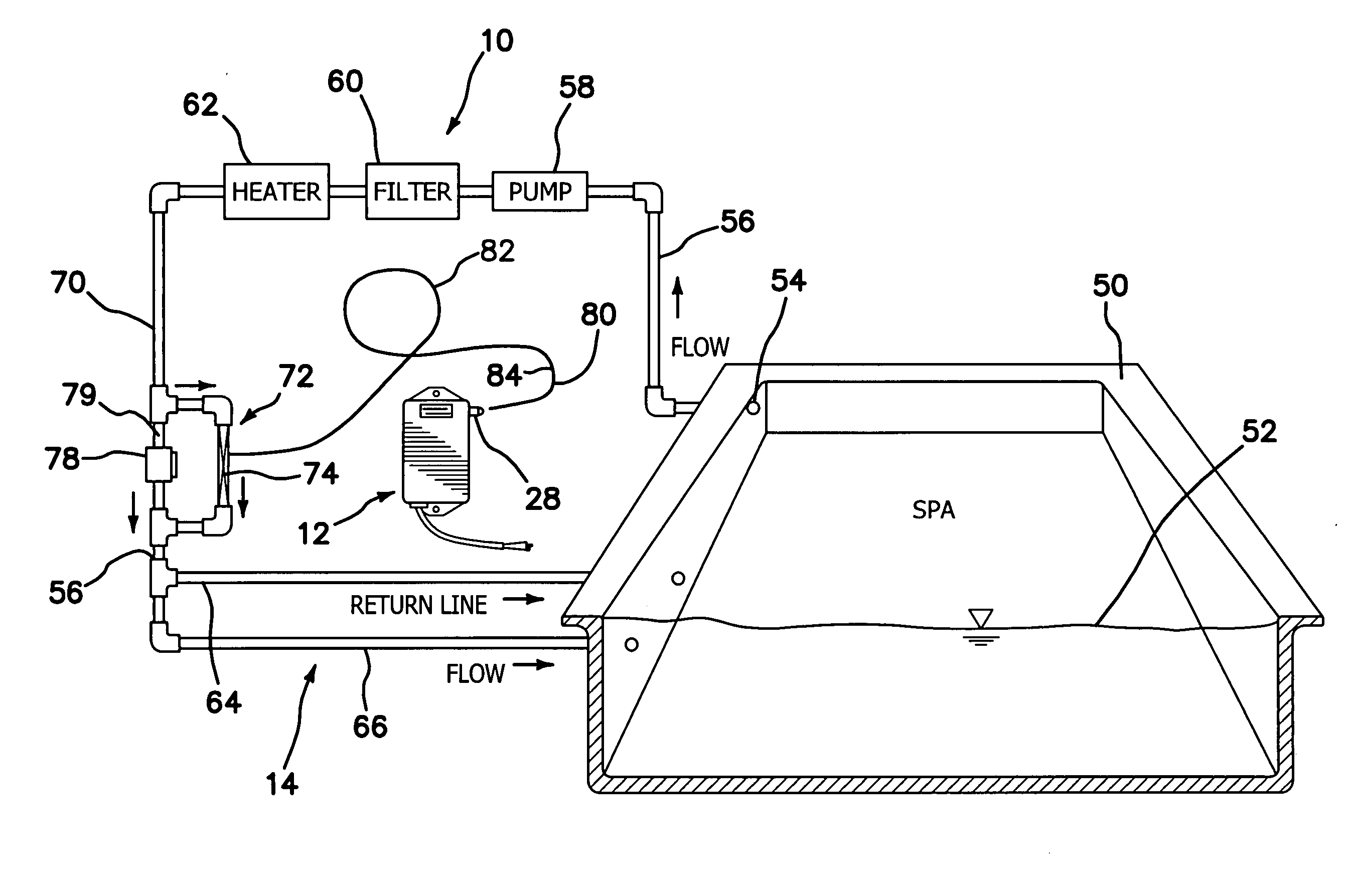
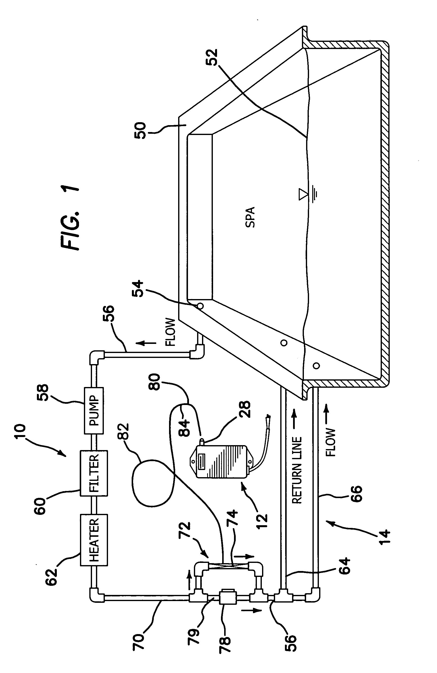
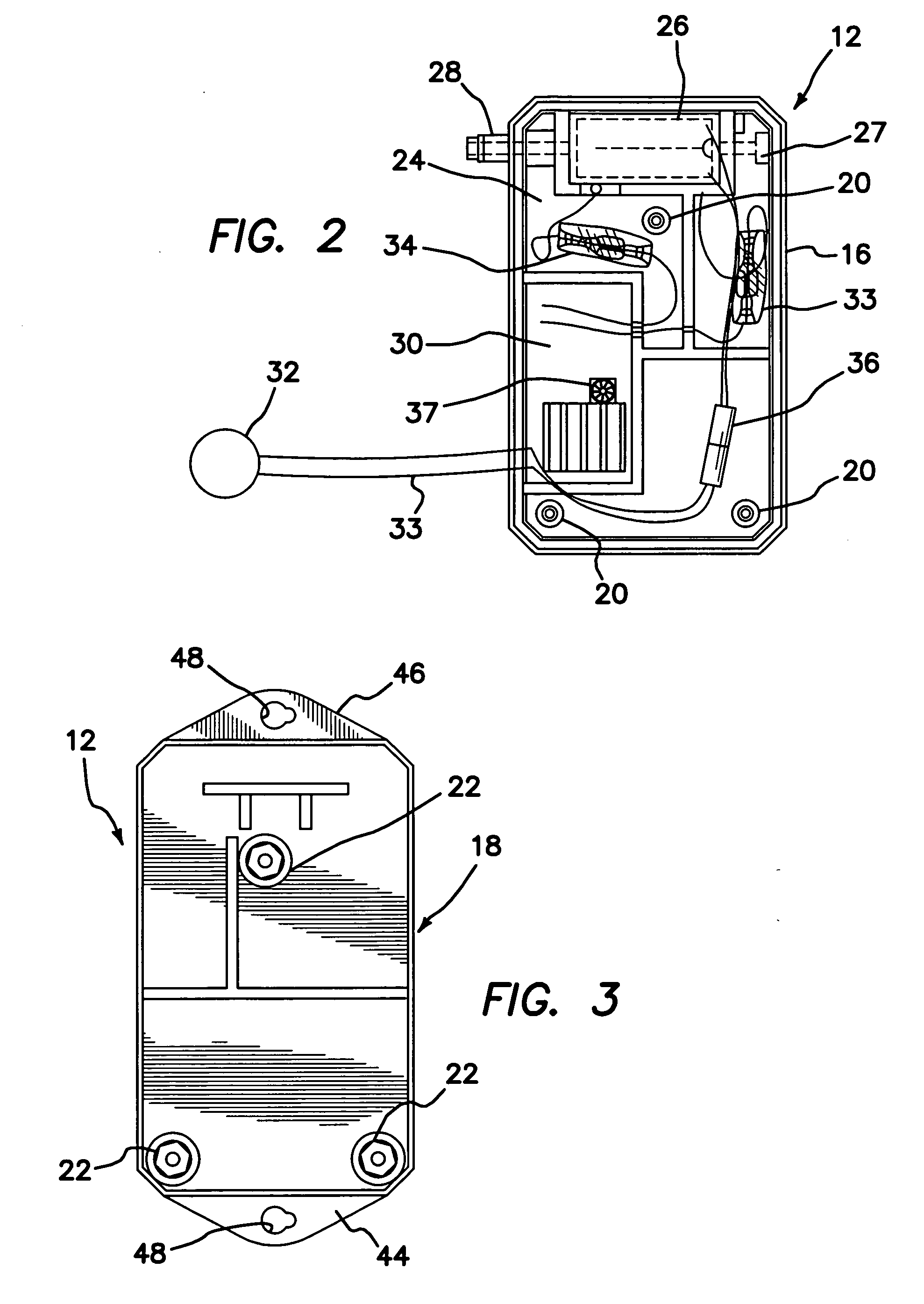
[0100]Referring now to the drawings 1-3, one configuration of the system of the present invention, shown generally at 10, includes an Corrosion Resistant Ozone Generator assembly housing shown generally at 12, and a transfer assembly, shown generally at 14. The Corrosion Resistant Ozone Generator assembly housing 12 is surrounded by a housing body 16 and a housing cover 18 which is adapted to be joined or connected to the housing body by coupling threaded inserts 20 through complimentary cover holes 22 with threaded screws (not shown).

[0101]With housing cover 18 secured to housing body 16, ozone generator 12 is contained within and protected by a compact, closed unit. Located within the space 24 between the housing body 16 and housing cover 18 is an Corrosion Resistant Ozone Generator 26. Ozone-containing gases produced by Corrosion Resistant Ozone Generator 26 from air entering housing body 16 through air inlet 27 exit the housing through housing outlet 28, which can be an integral...

example 2

[0109]This example describes the components of one embodiment of the Corrosion Resistant Ozone Generator 26 which can be used in the system of the present claims.

[0110]As shown in FIG. 4, the chip electrode assembly has a center wafer 101 made entirely of a dielectric; this wafer is a “spacer” wafer positioned between a top wafer 103 and a bottom wafer 105. In this embodiment the spacer wafer 101 is made of 96% alumina ceramic. The spacer wafer 101 has a substantially central opening 107. The top wafer 103, in this case also made of 96% alumina ceramic, has a segment of a proximal side of the wafer cut away from it 109, and the bottom wafer 105, made of 96% alumina ceramic, and having a segment of a distal side cut away from it 111.

[0111]Those of ordinary skill in the art will be aware that the spacer wafer, top wafer and bottom wafer may be comprised of other ceramic dielectrics or even other non-ceramic dielectrics; moreover, in other embodiments, one or more wafer may be comprise...

example 3

[0117]As shown in FIG. 5, the components shown in FIG. 4 are assembled to form the Corrosion Resistant Ozone Generator 26, as used in the embodiment of the system of the present invention shown in FIG. 1. The Corrosion Resistant Ozone generator is comprised of the three wafers, namely, a top wafer 103, center wafer 101 and bottom dielectric wafer 105, that are sandwiched together, with conductant metal tape or plates 121 (not shown) and 121′ acting as electrodes and wires 123 and 123′ (not shown) connecting the plates to each pole of a high voltage source. The conductant plates or tape are located substantially centrally on each of the top surface of the top wafer and the bottom surface of the bottom wafer such that when assembled, they substantially superimpose upon each other and are in addition substantially centrally located with respect to the middle wafer 101 in alignment with to the central opening in the middle wafer, as shown in FIG. 5. These conductant plates are either ad...


PUM

PropertyMeasurementUnit
thicknessaaaaaaaaaa
thicknessaaaaaaaaaa
widthaaaaaaaaaa

Abstract

Corrosion Resistant Ozone Generators, including ozone generating chips, for various purposes including spas, pools and jetted tubs as well as methods for making and using such Corrosion Resistant Ozone Generators.

Description

[0001]The present patent application claims priority to[0002]U.S. Provisional Patent Application No. 61 / 261,192, filed Nov. 13, 2009, which is hereby incorporated by reference herein in its entirety.FIELD OF THE INVENTION[0003]The present invention relates to systems, apparatus, and methods of purifying and disinfecting waters used in various applications, including but not limited to spas, jetted tubs, Jacuzzis, whirlpools, wave pools, baths, ponds, water tanks, swimming pools and the like. More particularly, the invention relates to apparatus and methods specifically configured and adapted for the treatment, for example, for the purification, of waters used in spas, jetted tubs, Jacuzzis, whirlpools, wave pools, baths, ponds, water tanks, swimming pools and the like. In other embodiments, the invention may relate to systems, methods and apparatus for, without limitation, disinfecting foods (for example, by spraying and / or washing produce with a liquid containing a non-toxic disinf...

Claims


Application Information

Patent Timeline
Patent Type & Authority Applications(United States)
IPC IPC(8): C02F1/78H05K13/00A61L2/20
CPCC01B13/11C01B2201/24C01B2201/34C01B2201/72Y10T29/49124C02F1/001C02F1/78C02F2103/42C01B2201/90Y10T29/42C02F1/4672C02F2201/46105C02F2303/04
Inventor CANNAVINO, JOSEPH A.MARTIN, FRANK G.
Owner CUSTOM MOLDED PROD
Why Eureka
Try Eureka