Up and down conversion systems for improved solar cell performance or other energy conversion
What is Al technical title?
Al technical title is built by PatSnap Al team. It summarizes the technical point description of the patent document.
a solar cell and conversion system technology, applied in the field of up and down, can solve the problems of uneven solar radiation spectrum energy distribution, unbalanced hole-electron pair production, and virtually non-responsive solar cell assembly to ultraviolet ligh
Active Publication Date: 2011-06-02
IMMUNOLIGTHT LLC +1
View PDF28 Cites 75 Cited by
Summary
Abstract
Description
Claims
Application Information
AI Technical Summary
This helps you quickly interpret patents by identifying the three key elements:
Problems solved by technology
Method used
Benefits of technology
[0023]In another embodiment, there is provided a conversion element. The conversion element includes a first plurality of particles which upon radiation from a first radiation source radiate at a higher energy than the first radiation source, and includes a secon
Problems solved by technology
When a solar cell device is excited by the radiation of the sun or artificial light, the photons absorbed by semiconductor material result in unbalanced hole-electron pair production.
However, the energy distribution of the solar radiation spectrum is uneven.
On the other hand, the solar cell assembly is virtually non-responsive to the ultraviolet (λ<4 00 nm), i.e. silicon cannot efficiently convert this ultraviolet light.
Solar cells operate as quantum energy conversion devices, and are therefore subject to the “Thermodynamic Efficiency Limit.” Photons with an energy below the band gap of the absorber material cannot generate a hole-electron pair, and so their energy
Method used
Image
Click on the blue label to locate the original text in one second.
Reading with bidirectional positioning of images and text.
Examples
Embodiment Construction
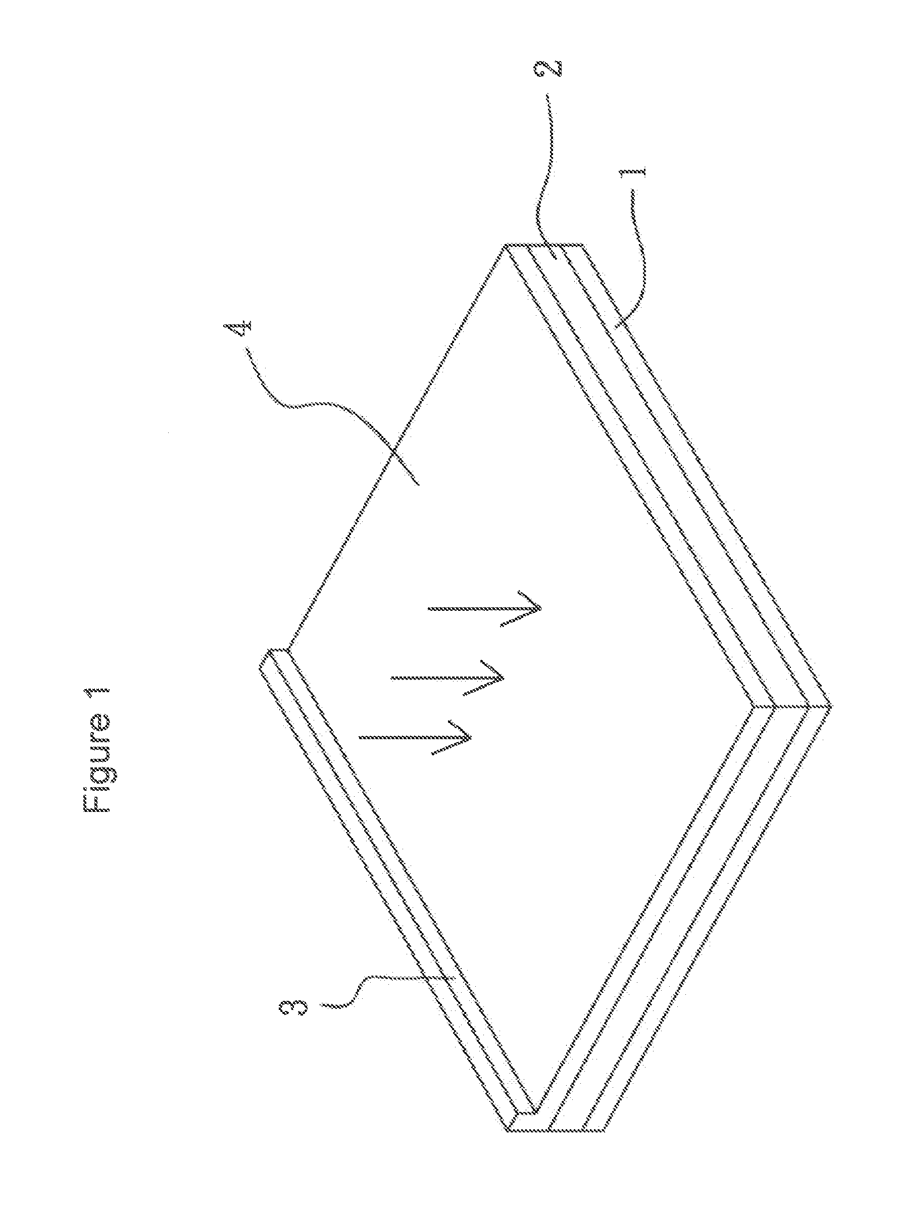
[0048]Reference will now be made in detail to the present preferred embodiment of the invention, an example of which is illustrated in the accompanying drawings, in which like reference characters refer to corresponding elements. FIG. 4 illustrates a power conversion system according to the present invention. With reference to FIG. 4, the power conversion system comprises a conversion element 10 and a conversion film 20.
[0049]In one embodiment of the invention, the power conversion system is exposed to solar radiation in terrestrial or extraterrestrial settings, and the solar energy is converted by the conversion film 20 into a wavelength or wavelengths where the conversion element 10 is designed to operate (e.g., the solar energy is converted to wavelengths close to the band gap energy of a semiconductor material in the conversion element 10).
[0050]In another embodiment of the invention, the power conversion system is exposed to high energy or ionizing radiation, and the high energ...
PUM
Abstract
A system and a conversion element for power conversion. The power conversion system includes a power conversion device which produces electric power upon illumination and includes a light conversion device which down-converts and up-converts a radiant source of energy into a specific energy spectrum for the illumination of the power conversion device. The conversion element includes a first plurality of particles which upon radiation from a first radiation source radiate at a higher energy than the first radiation source, and includes a second plurality of particles which upon radiation from the first radiation source radiate at a lower energy than the first radiation source. At least one of the first plurality of particles and the second plurality of particles can be at least partially metal coated.
Description
CROSS REFERENCE TO RELATED APPLICATIONS[0001]This application is related to Provisional Applications Ser. No. 60 / 954,263, filed Aug. 6, 2007, and 61 / 030,437, filed Feb. 21, 2008, and U.S. application Ser. No. 12 / 059,484, filed Mar. 31, 2008, the contents of which are hereby incorporated herein by reference. This application is also related to U.S. application Ser. No. 11 / 935,655, filed Nov. 6, 2007; and Provisional Applications Ser. No. 61 / 042,561, filed Apr. 4, 2008; 61 / 035,559, filed Mar. 11, 2008, and 61 / 080,140, filed Jul. 11, 2008, the contents of which are hereby incorporated herein by reference. This application is related to Provisional Application Ser. No. 61 / 161,328, filed Mar. 18, 2009, the contents of which are hereby incorporated herein by reference. This application is related to Provisional Application Ser. No. 61 / 371,549, filed Aug. 6, 2010, the contents of which are hereby incorporated herein by reference.[0002]This application is related to and claims priority unde...
Claims
Application Information
Patent Timeline
Application Date:The date an application was filed.
Publication Date:The date a patent or application was officially published.
First Publication Date:The earliest publication date of a patent with the same application number.
Issue Date:Publication date of the patent grant document.
PCT Entry Date:The Entry date of PCT National Phase.
Estimated Expiry Date:The statutory expiry date of a patent right according to the Patent Law, and it is the longest term of protection that the patent right can achieve without the termination of the patent right due to other reasons(Term extension factor has been taken into account ).
Invalid Date:Actual expiry date is based on effective date or publication date of legal transaction data of invalid patent.
IPC IPC(8): H01L31/00H01L31/0232G02B6/02G02B7/02
CPCY02E10/52H01L31/055
Inventor BOURKE, JR., FREDERIC A.FATHI, ZAKSTANTON, IAN NICHOLASTHERIEN, MICHAEL J.