In another option, the dehumidification subsystem may include a screen or related porous device through which a breeze, the wind or the like can carry the
ambient air. Porous members located in the dehumidification subsystem allow the wicking of water (in the form of
humidity in the
ambient air) into a flowpath that drains into an appropriate trough or related
sluice. Motors, winches or the like can be used to reposition the screen of the dehumidification subsystem so that it best aligns with the
prevailing winds to take best
advantage of the
system's evaporative capabilities.
The system may further include a positioning mechanism that permits movement of at least the RO subsystem through various depths of the
saline water supply. In this way, briny water being discharged from the RO subsystem is done so over a larger space, thereby reducing the likelihood of the briny water corrupting the
water supply. In the present context, briny water is any such water that, when reintroduced into the supply from where it came, has a higher salt concentration that of the surrounding supply. For example, if the
saline water supply is the sea, ocean or related body of water, the briny water would be that produced by the higher
salinity RO subsystem
discharge that is in turn placed back into the body of water. Thus, one purpose of
continuous operation of the positioning mechanism associated with the RO subsystem during the lowering and raising of the RO unit is that the briny concentrate leaving the RO unit is dispersed over a very large area and therefore would not result in a
significant difference in the
salinity of the water through which is passes. An additional benefit is that this would prevent debris from accumulating on the surface of the membrane in the RO unit.
According to another aspect of the present invention, a shipboard
water desalination apparatus is disclosed. The apparatus includes an RO subsystem with a
saline water inlet, a purified water outlet and a membrane, a dehumidification subsystem and one or more storage tanks for the collection of purified water. As with the previous aspect, the membrane allows preferential passage of water relative to salt in a saline water supply such that the water that passes through the membrane has a reduced
salt content (as well as that of other contaminants) relative to that of the supply. The RO subsystem is further configured as a passive device. In this way, pumps or related equipment that are needed in conventional RO system to attain the high inlet pressures necessary to force the water through the membranes are not required, as a
hydrostatic pressure of the saline water supply present at the saline water inlet (due, for example, to at least the inlet of the apparatus being situated at a significant subsurface depth) is sufficient to pass water from the water supply through the membrane. Such passive pressure may be produced from the system operating at depth where water is at
maximum density, such as where the
water temperature is as close to 2° Celsius as possible. As with the previous aspect, continuous movement of the RO unit eliminates the accumulation of debris on the surface of the RO membrane that could otherwise cause problems in stationary RO units in use. Also as with the previous aspect, the dehumidification subsystem can at least partially condense water present in an
ambient air supply. Preferably, the dehumidification subsystem avoids the use of salinated water as a cooling agent to reduce the risk of subsystem
contamination and related
fouling. In addition, using a cold water supply (such as the purified water from the RO subsystem) as the source of the temperature differential allows the dehumidification system to operate around the
clock (i.e., experience a larger
duty cycle) with greater efficiency because even at night (with a concomitantly cooler
air temperature), the temperature differential would still be enough to allow subsystem operation, as the relatively cold temperature of the water accumulated in a container or containers used in the RO subsystem helps provide a temperature differential that makes the dehumidification unit of the dehumidification subsystem work.
Optionally, introducing the RO subsystem includes moving the RO subsystem during its operation as a way to reduce brine concentration in the adjacent water, in effect spreading out the briny water flowing out of the RO unit over a larger area. In one form, the condensing may include using one or more of the saline water supply and the purified water produced in the RO subsystem as a cooling liquid in the
heat exchanger, which is preferably configured as a liquid-air
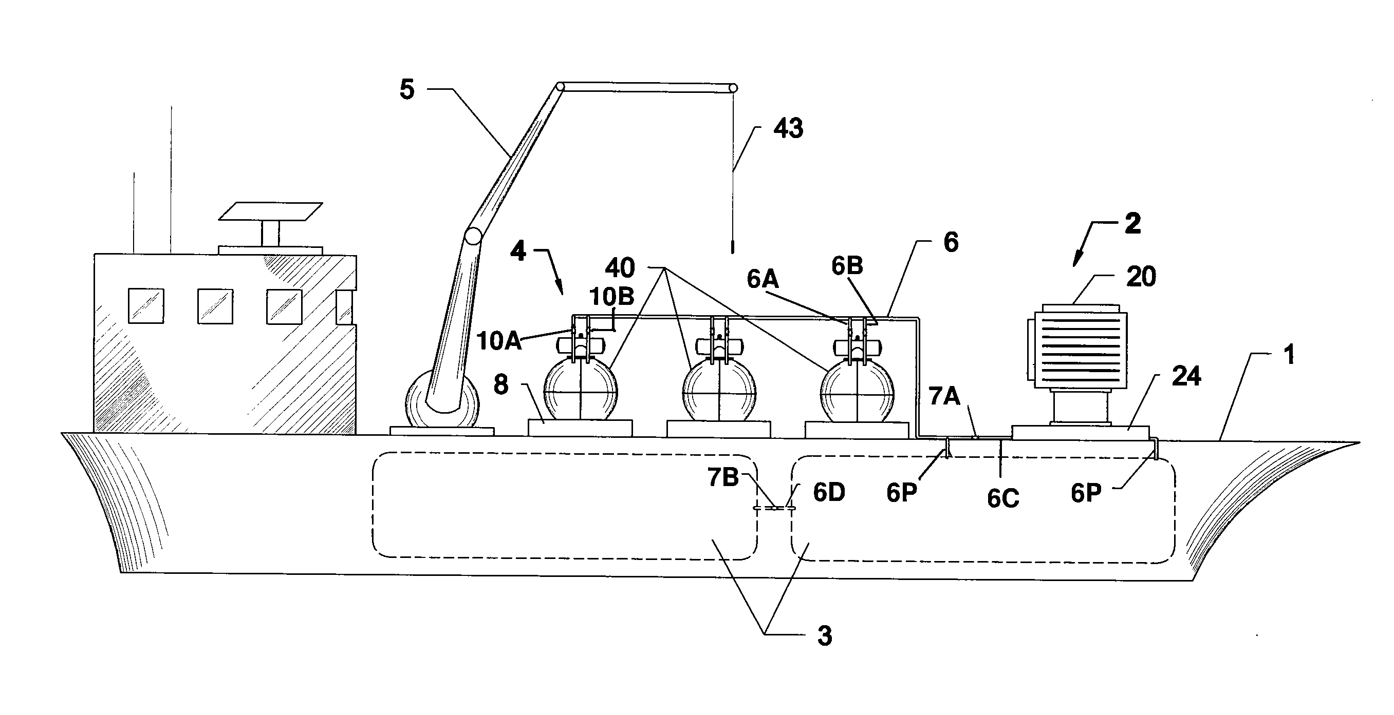
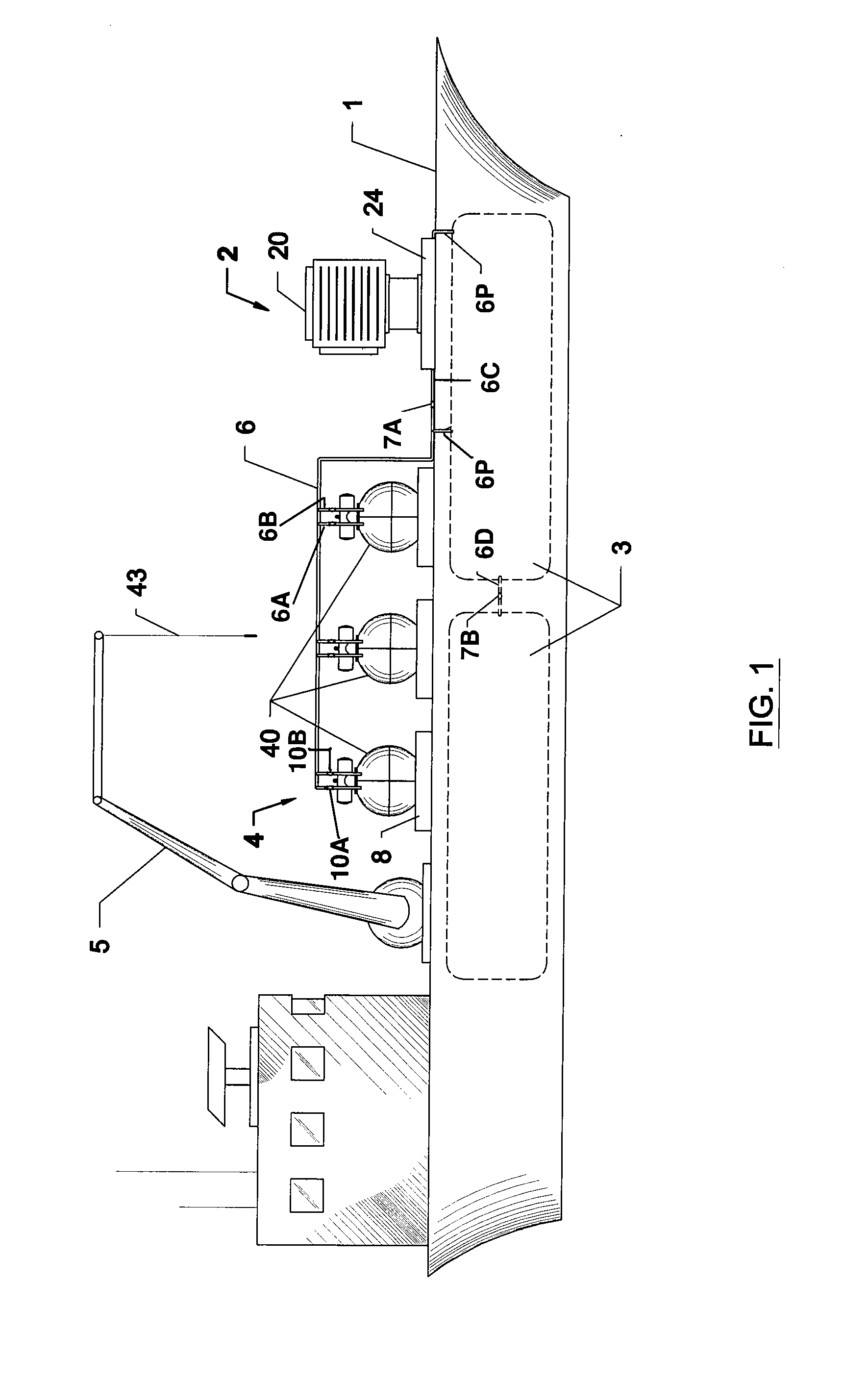
heat exchanger. In a preferable option, the RO and dehumidification subsystems, as well as the
storage tank, are mounted to or otherwise integrated onto a ship or related
watercraft. As previously discussed, the
storage tank may be made up of a series of separate tanks that can be interconnected through appropriate
piping, valving and pumping apparatus. Placement of various storage tanks around the ship (such as around the ship periphery) can be used with such apparatus to advantageously promote ship balance by moving the stored potable water between the various tanks. In another option, the heat exchanger can be positioned, such as by rotating it relative to the ship or the supply of humid air to maximize heat
exchange interaction.
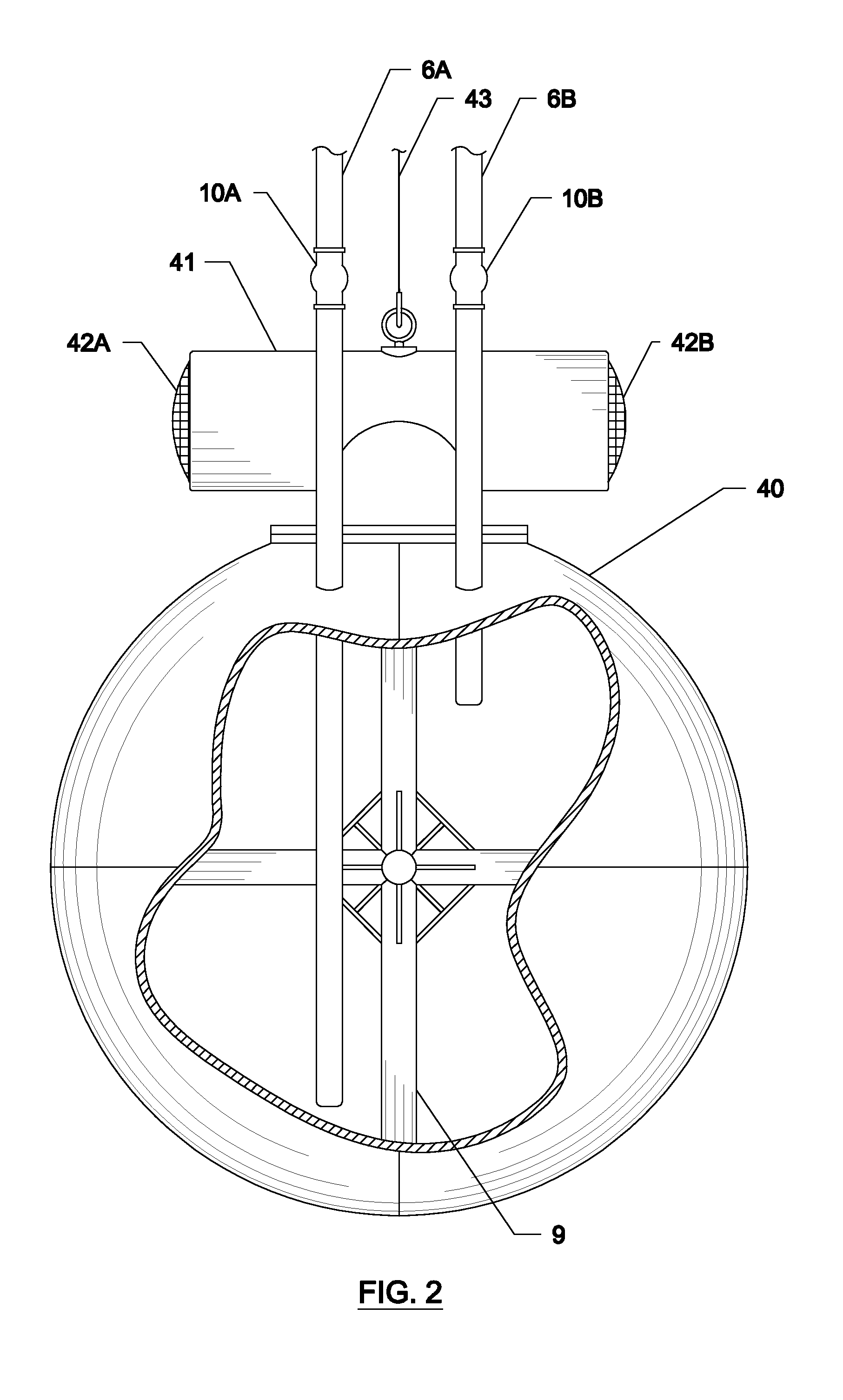
In another option, the containers used to collect the purified RO water in the RO subsystem can be evacuated to a low pressure prior to being lowered into the ocean or related saline water supply. In one form, the pressure can be reduced to less than about 1.47 psi to reduce or eliminate the
back pressure in the container, thereby allowing it to fill more completely during operation without additional depressurizing being necessary during the cycle. In another option, cleaning steps may be undertaken to eliminate or otherwise reduce the likelihood of
fouling from contaminant build-up, such as salt,
organic matter or the like. In this way, the purified water can be additionally treated to provide disinfection to eliminate microorganisms. Likewise, additional
filtration devices can be used to remove suspended
particulates. After such treatment, the purified water collected in the storage container can then pumped out for subsequent use by the dehumidification system, storage in the shipboard storage tanks, or both.

