Excimer lamp

a technology of exclamation lamp and discharge tube, which is applied in the direction of gas-filled discharge tube, fixed installation, lighting and heating apparatus, etc., can solve the problems of creeping discharge along the surface of the discharge chamber, inability of construction to realize compact and simple luminous units, and inability to improve reliability, so as to achieve high emission output and high reliability

Active Publication Date: 2011-06-30
ORC MFG
View PDF1 Cites 7 Cited by
  • Summary
  • Abstract
  • Description
  • Claims
  • Application Information

AI Technical Summary

Benefits of technology

[0012]An object of the present invention is to provide an excimer lamp that has high reliability and prevents a creeping discharge even though a high voltage is applied to obtain a high emission output.

Problems solved by technology

At this time, there is a possibility of an electrical breakdown and a creeping discharge along a discharge chamber surface, because of the application of several kilo-volts between the electrodes.
However, such a construction cannot realize a compact and simple luminous unit since the conventional excimer lamp with the dual-cylinder tube structure is necessarily large.
To emit an excimer ray having high-radiation output characteristics, a gas pressure should be set at a high pressure (and especially an applied voltage should be set to a high voltage), however, a measure or step that only covers the electrodes with an insulation material will not cause reliability to improve.
On the other hand, in an excimer lamp that applies high voltage to obtain high output of emitted light, there is a possibility of electric breakdown occurring through a slight clearance between the discharge chamber and the coating layer, though an electrode coating layer consisting of glass is heated and tightly attached to the electrodes.
For example, when an aluminum foil is used as an electrode, it is difficult to coat the electrode in accordance with the electrode-shape without a clearance since the temperature of the heated glass cannot be increased sufficiently due to the low melting point of aluminum.
Also, if the thermal expansion coefficient is different between the discharge chamber and the coating layer, stress occurs due to thermal hysteresis based on a blinking of the lamp, so that there is a danger that slight cracks leading to an electric breakdown may gradually occur in a boundary surface.
Also, when laminating or covering by methods such as thermal spraying of glass materials, bubbling and cracking occur, which creates the danger of an electric breakdown occurring due to the bubbling and cracking.

Method used


Image

  • Excimer lamp
  • Excimer lamp
  • Excimer lamp

Examples


first embodiment

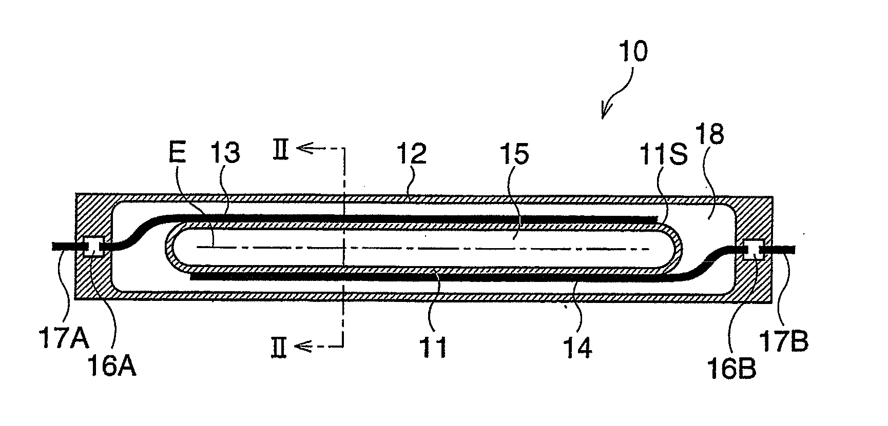
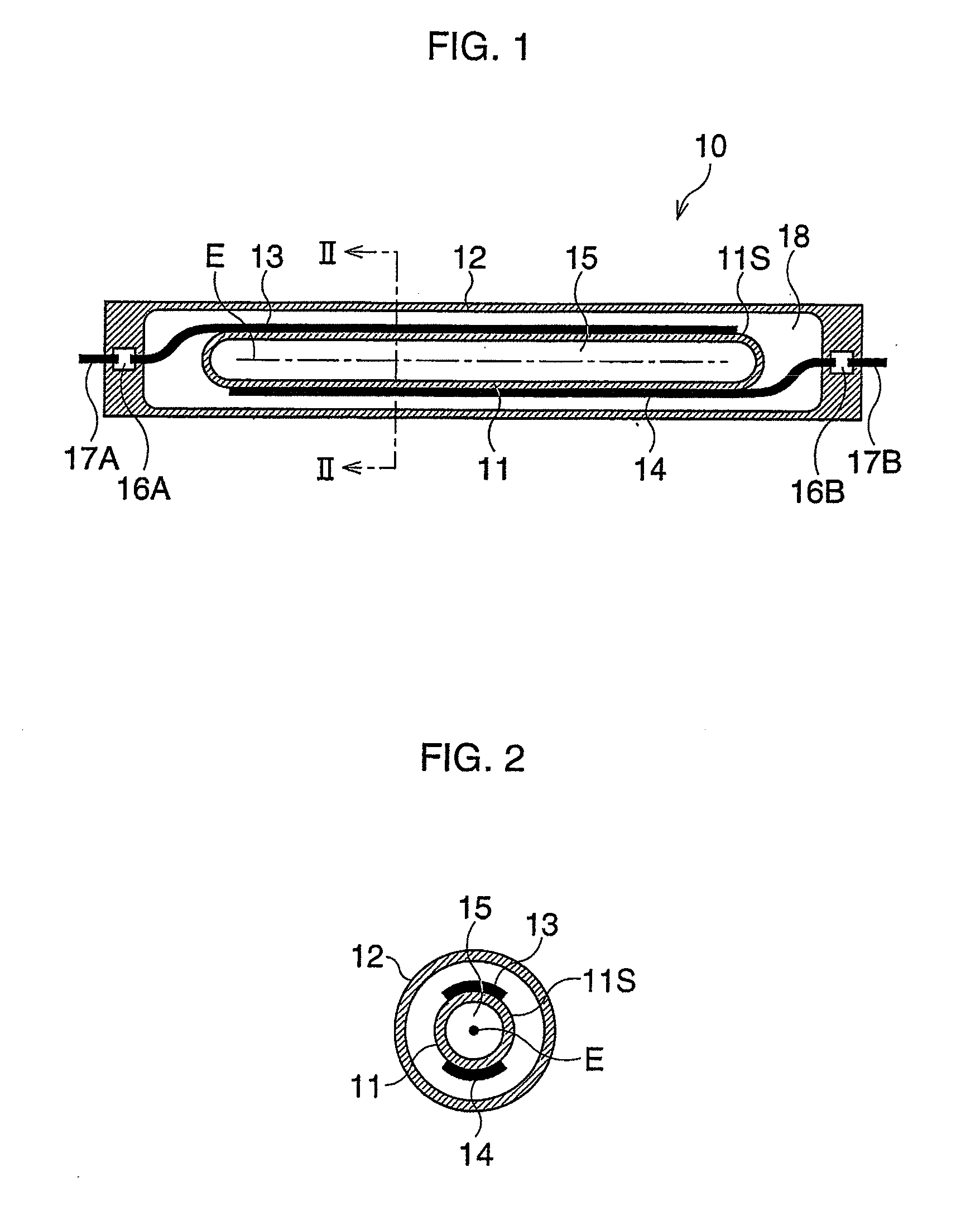
[0024]FIG. 1 is a cutaway side view along an axis of an excimer lamp according to the FIG. 2 is a schematic cross-sectional view associated with a radial direction, along II-II shown in FIG. 1.

[0025]A single-cylinder tubular excimer lamp 10 has a discharge chamber 11 consisting of quartz glass, and a cylindrical outer tube 12 consisting of quartz glass is coaxially provided so as to encompass or enclose all of the discharge chamber 11. A circular cylindrical space 18 (hereinafter called an “insulation space”) is formed between the discharge chamber 11 having hemispherical edge portions and the outer tube 12. A discharge gas that produces excimer molecules during discharge, such as xenon gas, is filled or enclosed in a discharge space 15 formed in the discharge chamber 11.

[0026]On the outer surface (exterior side surface) 11S of the discharge chamber 11, a pair of band-shaped electrodes 13 and 14, which extend along the lamp axis E, are arranged so as to be opposite one another, and...

second embodiment

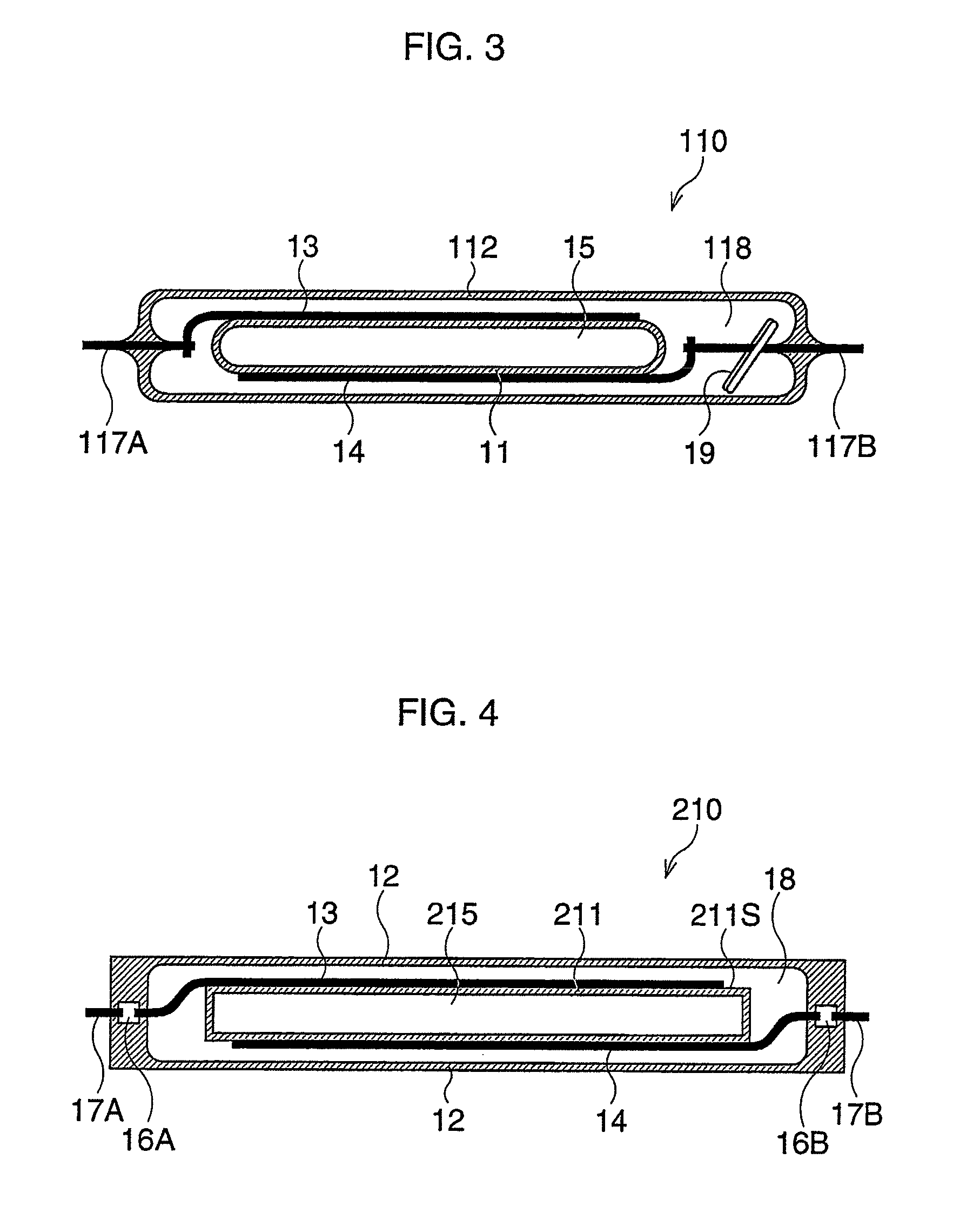
[0033]FIG. 3 is a cutaway side view of an excimer lamp according to the The excimer lamp 110 has a quartz glass discharge chamber 11 and an outer tube 112 composed of hard glass such as a tungsten glass. The hard glass has a heat expansion coefficient higher than that of the quartz glass, and metal lead wires 117A and 1178, such as tungsten wires, are connected to electrodes 13 and 14, and directly enclosed within the outer surface 112.

[0034]An insulation space 118 formed between the discharge chamber 11 and the outer surface 112 is subjected to be vacuum state. To form a vacuum space, gas in the discharge chamber 11 is first exhausted through an exhaust tube (not shown) provided on the outer surface 112 by utilizing a turbo-molecular pomp such that high vacuum state is produced, and the exhaust tube is then shut. Next, a barium getter 119 is scattered and adhered to the inner wall of the outer surface 112 by a high-frequency induction heating. Thus, the few impure gases that were ...

third embodiment

[0037]FIG. 4 is a cutaway side view of the excimer lamp according to the A discharge chamber 211 in the excimer lamp 210 is composed of ceramics such as alumina, and electrodes 13 and 14 are arranged on the outer surface 211S so as to be opposite from one another. In the insulation space 18 formed between the discharge chamber 211 and the quartz glass outer tube 12, an arc-suppression gas such as a mixing gas consisting of N2 and O2 is enclosed. Thus, creeping discharge in the outer tube 12 is prevented.

[0038]Since the discharge chamber 211 is made of ceramics with heat resistance and relatively high strength, an input voltage can be increased, so that the intensity of light increases, thereby increasing the service life of use for the lamp. Furthermore, a gas reacting with a quartz discharge chamber, such as a fluorine gas, may be enclosed in the discharge space 215. Thus, excimer light having a specific wavelength, which is not obtained from the quartz discharge chamber, can be e...


PUM


Abstract

An excimer lamp has a single tubular discharge chamber configured to enclose a discharge gas that is a noble gas or a mixing gas consisting of a noble gas and a halogen gas; a pair of electrodes configured to be arranged along opposite sides of the exterior surface of the discharge chamber; and an outer tube configured to cover the discharge chamber and the electrodes. Excimer molecules are produced by either dielectric barrier discharge or capacitive-coupled high-frequency discharge. An interior of a space formed between the outer tube and the discharge chamber is either in a vacuum state that is necessary and sufficient for preventing discharge, or is filled with an arc-suppression gas.

Description

CROSS REFERENCE TO RELATED APPLICATIONS[0001]This is a continuation application of PCT Application No. PCT / JP2009 / 054232, filed on Feb. 27, 2009, designating the United States of America, the disclosure of which, including the specification, drawings, and claims, is incorporated herein by reference in its entirety.[0002]The disclosure of Japanese Patent Application No. 2008-065311, filed on Mar. 14, 2008, including the specification, drawings, and claims, is further incorporated herein by reference in its entirety.BACKGROUND OF THE INVENTION[0003]1. Field of the Invention[0004]The present invention relates to an excimer lamp as an ultraviolet light source that is mainly used for industry. Especially, it relates to a structure of an excimer lamp that radiates an excimer ray by either dielectric barrier discharge or capacitively-coupled high-frequency discharge.[0005]2. Description of the Related Art[0006]As an excimer lamp for industry, a xenon lamp having a wavelength of 172 nm is k...

Claims


Application Information

Patent Timeline
Patent Type & Authority Applications(United States)
IPC IPC(8): H01J61/12H01J11/00H01J61/26H01J61/34H01J65/00
CPCH01J61/16H01J65/046H01J61/34
Inventor YASUDA, MAKOTOKOBAYASHI, GO
Owner ORC MFG
Why Eureka
Try Eureka