
MRI and ultrasound guided treatment on a patient

Inactive Publication Date: 2011-06-30
IMRIS
View PDF6 Cites 32 Cited by
  • Summary
  • Abstract
  • Description
  • Claims
  • Application Information

AI Technical Summary

Benefits of technology

[0078]The arrangement described herein correlates the outstanding high resolution MR images with the images that can be obtained in the presence of MR or LINAC. The present invention relates to the fact that a common platform for characterizing the real time motion of the soft organs, during breathing, cardiac or other functions, can be superimposed or fused on a MR CINE and ultrasound image to use for planning and treatment of diseases with radiation therapy or brachytherapy. In a further aspect, there is provided a dual 3-D ultrasound transducer with an incorporated MR radio frequency coil structure can be also use for real time tracking the navigation of the biopsy or brachytherapy device into the targeted area. By combining the superior image quality of the MR CINE and superimposing in real time the 3-D US image, the navigation of the biopsy and brachytherapy devices can yield the desired positional accuracy without guessing. By utilizing the RF coils to obtain the MR CINE image and the 3-D US transducer for US image and fusing them together the system provides real time navigation combined image with superior resolution than the US image alone.
[0089]Ultra sound is much more flexible than MRI but has much lower image quality. The idea of registering the MRI image to the US is to improve the image quality and retain the flexibility.

Problems solved by technology

Even though MRI provides good location of the tumor at the time of the measurement, these images are normally recorded two to three days prior to the treatment and so may not be completely representative of tumor location on the day of treatment.
This produces collateral damage and may have a significant impact of the quality of life of the patient.
An additional challenge to effective radiation treatment and other treatment actions is the effect of motion of the tumor or other region of interest in the body due to respiratory motion, cardiac motion, peristalsis, digestive system actions and other bodily functions.
This can result in significant movement of the adjacent body parts so that tumor masses can move making the continuous accurate targeting for treatment difficult.
In addition to the above issues in relation to external radiation therapies, breathing, cardiac, or other unwanted motion also poses a problem during the MR interventional, biopsy and brachytherapy procedures where a probe acting to effect the action required must be accurately located.
Thus, during the insertion of the biopsy device, the soft organ can be moved and thus the biopsy device will miss the targeted area.
The error of positioning these devices is accelerated during a brachytherapy procedure, such as in the prostate where 12 to 18 tubes have to be inserted in the prostate for a treatment depending on the size and location of the lesion.
The physician can perform the insertion of these tubes under MRI guidance but again no real time monitoring of the insertion of the tubes into the area to be treated is available.
Once again, no real time navigation and tracking motion is available during the insertion of the brachytherapy tubes in the targeted treatment area.
In general major MR modalities like magnetic resonance imaging are usually incompatible with other imaging modalities like CT, X-ray, PET, SPECT and LINACs which are utilized for radiation therapy treatment.
Unfortunately due to the ferromagnetic materials that are part of a LINAC, it can not coexist at the same space as the MR system due to the safety concerns.
Thus the two can co-exist but this may not be the ideal solution since there are many restrictions if a combined system is developed.
The problem with this is the difficulty of combining linear accelerators and MRI.
This arises because the magnetic field generated by the magnet of course interferes with the operation of the linear accelerator to an extent which cannot be readily overcome.

Method used


Image

  • MRI and ultrasound guided treatment on a patient
  • MRI and ultrasound guided treatment on a patient
  • MRI and ultrasound guided treatment on a patient

Examples


Embodiment Construction

[0096]Reference is made to the following published applications of the present Applicant, the disclosures of which are incorporated herein by reference and to which reference should for further details of the constructions described schematically herein:

[0097]US20080039712A1 published Feb. 14, 2008 and entitled Movable Integrated Scanner for Surgical Imaging Applications;

[0098]US20090124884A1 published Feb. 14, 2008 and entitled CONTROL OF MAGNETIC FIELD HOMOGENEITY IN MOVABLE MRI SCANNING SYSTEM;

[0099]US20090306495A1 published Dec. 10, 2009 and entitled PATIENT SUPPORT TABLE FOR USE IN MAGNETIC RESONANCE IMAGING;

[0100]US20090306494A1 published Dec. 10, 2009 and entitled SYSTEM FOR MAGNETIC RESONANCE AND X-RAY IMAGING.

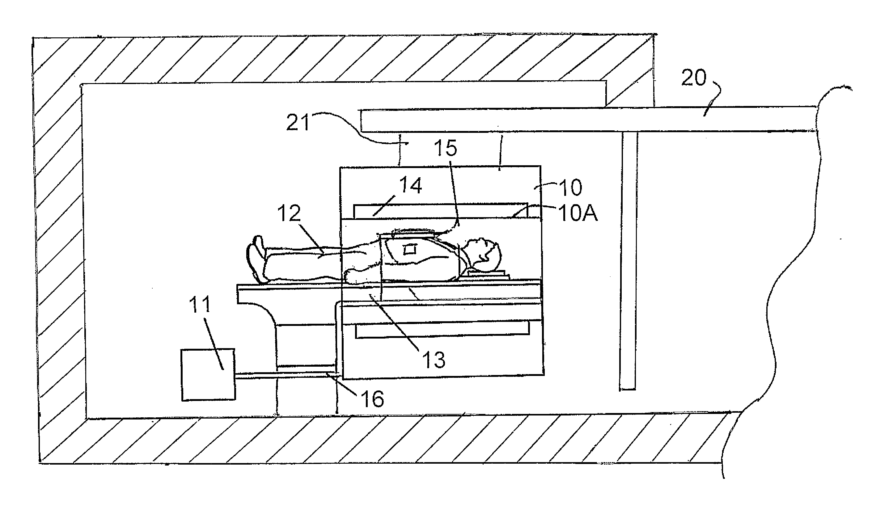
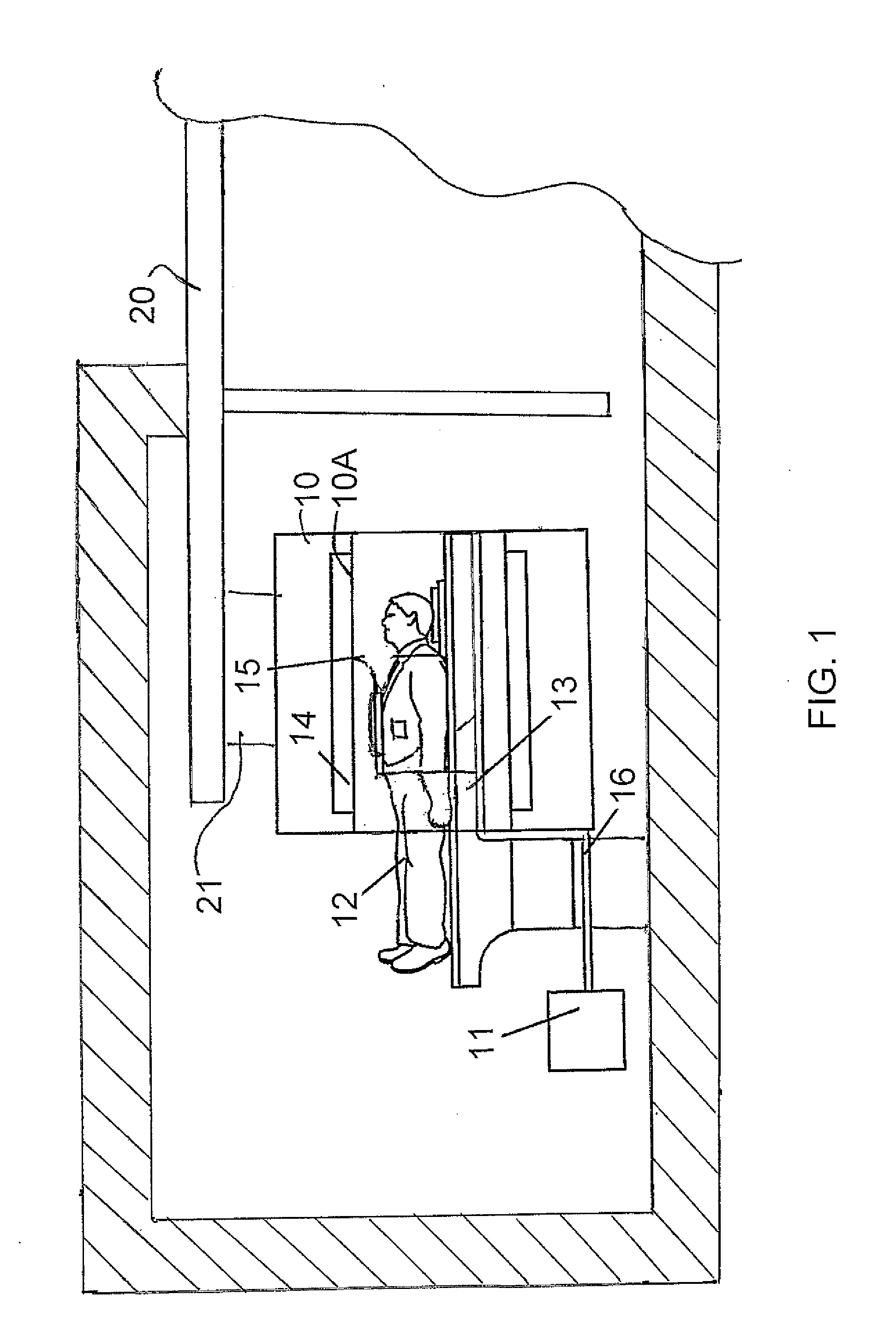
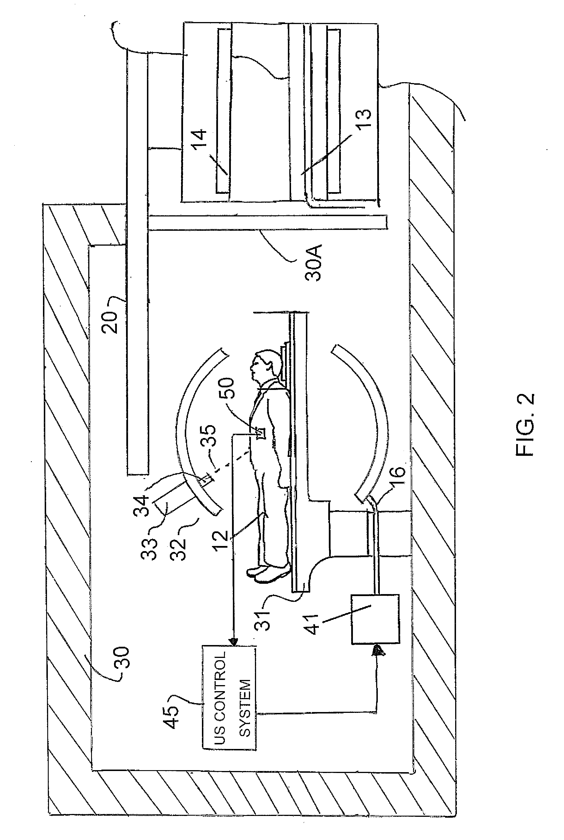
[0101]In FIG. 1 is shown schematically a magnetic resonance imaging system which includes a magnet 10 having a bore 10A into which a patient 12 can be received on a patient table 13. The system further includes an RF transmit body coil 14 which generates a RF field wit...


PUM


Abstract

A method is provided for guiding a procedure on a region of interest in a body part of patient, where the body part moves within the patient by breathing, cardiac or other action. The procedure includes radiation therapy, or guidance of a probe for example for biopsy or brachytherapy. The method includes using an MRI system to obtain an MR image of the body part, during the procedure on the body part of the patient, obtaining real time ultrasound images of the body part of the patient as the body part moves within the body of the patient, registering the MR image of the body part with the ultrasound image of the body part so as to locate the region of interest in the ultrasound image of the body part and using the registered images to target the action to the region of interest as the body part moves.

Description

[0001]This application claims the benefit under 35 U.S.C. 119 of the filing date of Provisional Application Ser. No.: 61 / 290,070 filed Dec. 24, 2009.[0002]This invention relates to MRI and ultrasound guided treatment on a patient.BACKGROUND OF THE INVENTION[0003]A radio therapy device generally includes a linear electron beam accelerator which is mounted on a gantry and which can rotate about an axis which is generally parallel to the patient lying on the patient couch. During the radiation therapy, the patient is treated using either an electron beam or an X-ray beam produced from the original electron beam. The electron or X-ray beam is focused at a target volume in the patient by the combination of the use of a collimator and the rotation of the source around the patient. The patient is placed on a couch which can be positioned such that the target lesion can be located in the plane of the electron beam as the gantry rotates in two directions.[0004]The objective of the radiation ...

Claims


Application Information

Patent Timeline
IPC IPC(8): A61B5/055
CPCA61B8/00G01R33/4814A61B8/4245A61B8/4254A61B8/4416A61B19/5225A61B2017/3405A61B2017/3413A61B2019/5236A61B2019/5238A61B2019/5276A61B2019/5289A61N5/1049A61N5/1067A61N2005/1055A61N2005/1058G01R33/3415G01R33/4808A61B8/08A61B90/37A61B2090/364A61B2090/374A61B2090/376A61B2090/378
Inventor PETROPOULOS, LABROSSAUNDERS, JOHN K.
Owner IMRIS
Learn More