Electric welding of aluminium or aluminium alloy

a technology of aluminium alloy and electric welding, which is applied in the direction of welding/cutting media/materials, welding apparatus, manufacturing tools, etc., can solve the problems of poor weld quality, inability to weld, and difficult point welding of aluminium, so as to reduce the effect of a magnetic field thereon and reduce the effect of the magnetic field

Inactive Publication Date: 2011-07-14
EFD INDUCTION AS
View PDF14 Cites 3 Cited by
  • Summary
  • Abstract
  • Description
  • Claims
  • Application Information

AI Technical Summary

Benefits of technology

[0020]According to one inventive feature of the invention, the adverse effect which is caused by said magnetic field area was countered by the welding wire not being fed in the conventional manner with direct current, but with intermediate frequency or high frequency alternating current instead. This largely solved the problem related to the “blowing” effect the magnetic field had on the welding arc. As shielding gas, argon was used in the tests, although other shielding gases could have been used. Such alternating current should have such a high frequency that the minimum frequency is set as a function of the prevailing magnetic field. A symmetrical alternating current in the arc will reduce the effect of a magnetic...

Problems solved by technology

Point welding of aluminium is more difficult than point welding of steel because the basic material easily sticks to the pressure electrodes of copper alloy.
It is known that there are a number of practical problems involved in carrying out 5 electric welding of aluminium.
Welding of aluminium rails in a magnetic field, often a very strong magnetic field, for example, 100 Gauss or stronger because of substantial direct currents flowing in the rails, generally make welding impossible, which is due to the thus absent ignition of the is arc.
In weaker magnetic fields, asymmetric welding will be produced and thus poorer weld quality.
Welding of aluminium in magnetic fields is therefore generally problematic.
Moreover, in general during the welding of aluminium it has however been found difficult to obtain a satisfactory weld because the arc has had a tendency to move to an area adjacent to the weld joint under formation.
However, such a solution proved to be awkward and hazardous because of the powerful magnetic field that could affect machining tools, but not least it was impractical because oxide layers are in any case formed almost immediately on aluminium or aluminium alloy.
However, this was not the only challenge that was see...

Method used


Image

  • Electric welding of aluminium or aluminium alloy
  • Electric welding of aluminium or aluminium alloy
  • Electric welding of aluminium or aluminium alloy

Examples


Embodiment Construction

)

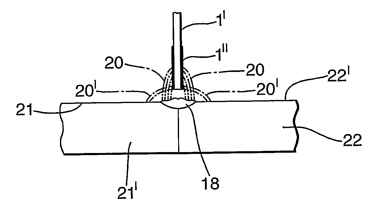
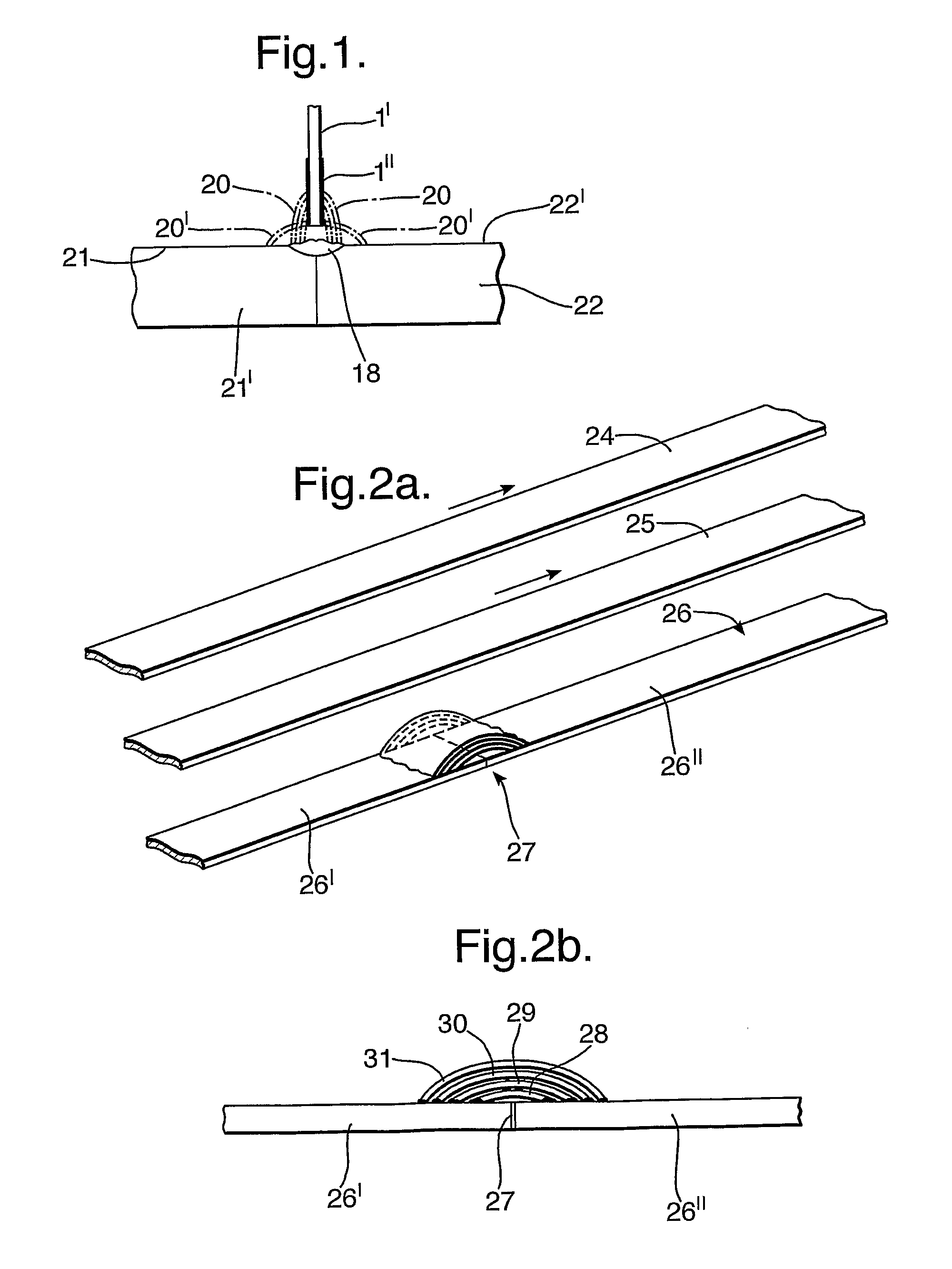
[0040]As mentioned initially, it has, in connection with the method and apparatus for use in electric welding of aluminium or aluminium alloy, been established that such metal adjacent to a weld joint under formation has an oxide layer. During the welding process, a free end 1′ of the welding wire 1 must be supplied with a surrounding shielding gas via suitable wire guide 2 in a welding gun 3.

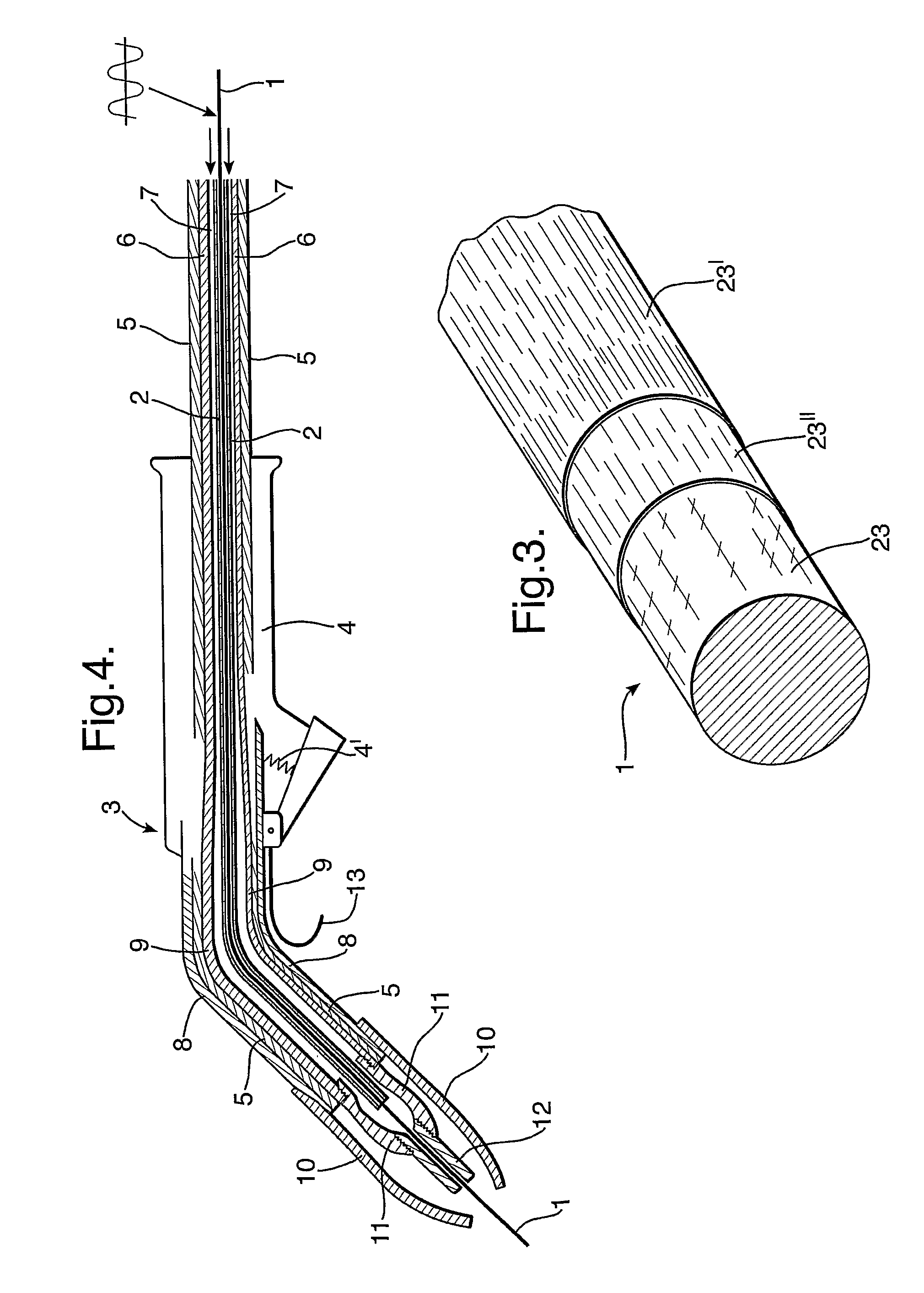
[0041]The welding gun 3 as shown in FIG. 4 is an ordinary GMAW welding gun comprising a gun handle 4, insulation 5, a flexible copper conductor 6 for current feed, space 7 for transporting shielding gas, the wire guide 2 for the welding wire 1, an outer copper tube 8 extending from the handle, an inner copper tube 9 for current feed, gas mouthpiece 10, gas nozzle 11, and contact tube 12 for feeding current to the welding wire. Furthermore, the welding gun is equipped with a hanging hook 13.

[0042]For the challenges that the invention is to solve in general, but particularly in a welding environ...


PUM

PropertyMeasurementUnit
Fractionaaaaaaaaaa
Fractionaaaaaaaaaa
Fractionaaaaaaaaaa

Abstract

Electric welding method is provided of aluminium or aluminium alloy in a magnetic field, the aluminium or aluminium alloy adjacent to a weld joint under formation has an oxide layer, and the free end of a welding wire is supplied with a surrounding shielding gas. Furthermore, a welding wire is used that comprises aluminium or aluminium alloy provided with an oxide-inhibiting coating, which forms the outer covering or sheath of the welding wire and/or that as said shielding gas there is used a shielding gas with oxygen incorporated therein, or that the shielding gas is supplied with oxygen during the welding process. When the process is carried out in a magnetic field, the minimum frequency of the welding current is selected as a function of the strength of the magnetic field. A method is also provided for producing the welding wire and necessary material conditions for a usable welding gun.

Description

FIELD OF INVENTION[0001]The present invention relates to aspects of electric welding of aluminium or aluminium alloy, and in particular where the welding is to be carried out in locations in which there is a powerful magnetic field, as, e.g., in aluminium electrolysis halls.[0002]More specifically, the invention relates to a method of electric welding as disclosed in the preamble of attached claim 1, a welding electrode for use in the electric welding process and as disclosed in the preamble of attached claim 12, an apparatus for electric welding and as disclosed in the preamble of respective attached claim 15, a method for producing welding wire and as disclosed in the preamble of attached claim 28, a use of the welding wire as disclosed in claim 33, a feedable and consumable welding wire as disclosed in claim 36, a device for producing welding wire and as disclosed in the preamble of attached claim 37, and a welding gun for use in the welding process and as disclosed in the preamb...

Claims


Application Information

Patent Timeline
IPC IPC(8): B23K9/16B23K35/22B05D5/12B05D1/36B05D3/00C25D7/06
CPCB23K9/0737B23K2203/10B23K9/08B23K2103/10
Inventor HORNAES, KETIL
Owner EFD INDUCTION AS
Why Eureka
Try Eureka