Enhanced Electrode Composition for Li ion Battery

a technology of li ion batteries and electrode compositions, which is applied in the direction of non-metal conductors, cell components, conductors, etc., can solve the problems of poor adhesion of cathode materials to current collectors, broken coatings, and inability to meet the requirements of conventional cathode compositions, so as to achieve enhanced battery performance and less conductive filler loading , the effect of less binder loading

Inactive Publication Date: 2011-07-14
JIANGSU CNANO TECHNOLOGY CO LTD
View PDF24 Cites 86 Cited by
  • Summary
  • Abstract
  • Description
  • Claims
  • Application Information

AI Technical Summary

Benefits of technology

[0020]Carbon nanotube-based compositions and methods of making an electrode for a Li ion battery are disclosed. It is an objective of the instant invention to disclose a composition for preparing an electrode of a lithium ion battery with incorporation of carbon nanotubes with more active material by having less conductive filler loading and less binder loading such that battery performance is enhanced. In one embodiment an enhanced electrode composition uses less binder, such as PVDF, thus allowing more electrode material, absolutely and proportionately, by weight, in the composition, which in-turn improves overall storage capacity. It is an objective of the instant invention to disclose a composition for preparing a cathode or anode of lithium ion battery with incorporation of carbon nanotubes such that enhanced battery performance by having less conductive filler loading, less binder loading and more active material.
[0021]As described in U.S. Provisional application, 61 / 294,537, the conductive paste based on carbon nanotubes is comprised of carbon nanotubes and preferred amount of liquid vehicle as dispersant and / or binder. During investigation, it was surprisingly found that selected liquid vehicles in various combinations can further reduce binder loading requirements. In some embodiments it is possible that PVP and PVDF may undergo strong interaction as shown by N. Chen in “Surface phase morphology and composition of the casting films of PVDF-PVP blend”, Polymer, 43, 1429 (2002). The addition of PVP altered the crystallization of PVDF and hence modified its mechanical and adhesion properties. The decreased of PVDF or combined PVP-PVDF can further improve the battery performance by allowing more addition of cathode material, so that improve the total capacity.

Problems solved by technology

However, with the use of carbon nanotubes, the conventional cathode composition can no longer satisfy the requirement due to the specialty of carbon nanotubes versus carbon black.
With carbon nanotubes, this composition will result in poor adhesion of cathode material on its current collector; alternatively, broken coatings when folded or wrapped.

Method used


Image

  • Enhanced Electrode Composition for Li ion Battery
  • Enhanced Electrode Composition for Li ion Battery
  • Enhanced Electrode Composition for Li ion Battery

Examples


example 1

Dispersion of Carbon Nanotubes in n-methyl pyrrolidone

[0047]30 grams of FloTube™ 9000 carbon nanotubes manufactured by CNano Technology Ltd., pulverized by jet-milling, were placed in 2-liter beaker. The tap density of this material is 0.03 g / mL. In another 500 milliliter beaker, 6 grams of PVP k90 (manufactured by BASF) was dissolved in 100 grams of n-methyl pyrrolidone. Then the PVP solution was transferred to the nanotubes together with 864 grams n-methyl pyrrolidone. After being agitated for an hour, the mixture was transferred to a colloid mill and ground at a speed of 3,000 RPM. A test sample was taken out every 30 min. for evaluation. Viscosity was taken at 25° C. using Brookfield viscometer for each sample and recorded; Hegman scale reading was taken simultaneously. Maximum dispersion was observed after milling for 90 minutes. The fineness of this paste reached better than 10 micrometer after 60 minutes of milling. This sample was named as Sample A.

example 2

Electrode Paste Preparation

[0048]A PVDF solution was prepared by placing 10 g of PVDF (HSV900) and 100 g n-methyl pyrrolidone in a 500-mL beaker under constant agitation. After all PVDF was dissolved, designated amount of paste (Sample A) from Example 1 and PVDF solution were mixed under strong agitation of 500-1000 RPM for 30 minutes. The resultant mixture was named Sample B.

[0049]In a separate container, desired weight of active materials such as LiFePO4 or LiCoO3 was weighed under nitrogen blanket. Selected amount of Sample B was also added to the active material and the mixture was stirred under high speed, e.g. 5000-7000 RPM for 5 hours. The resultant viscosity measured by Brookfield Viscometer should be controlled at 3000-8000 cps for LFP, or 7000-15000 cps for LiCoO3. The mixing and stirring was carried out in nitrogen environment and temperature not exceeding 40° C. The resultant sample was named Sample C.

example 3

Electrode Preparation

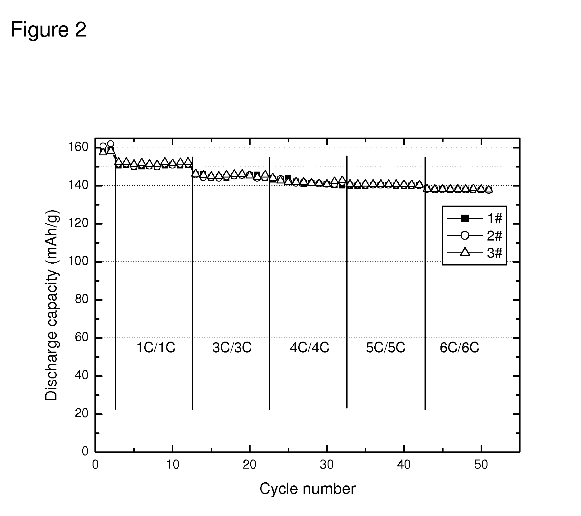
[0050]Clean aluminum foil was chosen as cathode current collector, and placed on a flat plexiglass. A doctor blade was applied to deposit a thin coating of Sample C of thickness of about 40 micrometer on the surface of aluminum foil. The coated foil was then placed in a dry oven at 100° C. for 2 hours. The cathode plate was then roll-pressed to form a sheet. A round disk of coated foil was punched out of the foil and placed in a coin battery cell. Lithium metal was used as anode, and the coin cell was sealed after assemble the cathode / separator / anode and injecting electrolyte. The made battery was then tested for various charging and discharging performance.


PUM

PropertyMeasurementUnit
diameteraaaaaaaaaa
tap densityaaaaaaaaaa
interstitial distanceaaaaaaaaaa

Abstract

Carbon nanotube-based compositions and methods of making an electrode for a Li ion battery are disclosed. It is an objective of the instant invention to disclose a composition for preparing an electrode of a lithium ion battery with incorporation of carbon nanotubes with more active material by having less conductive filler loading and less binder loading such that battery performance is enhanced.

Description

PRIORITY[0001]This application claims priority from U.S. Provisional Application 61 / 294,537 filed on Jan. 13, 2010 and incorporated herein in its entirety by reference.CROSS-REFERENCE TO RELATED APPLICATIONS[0002]This application is related to U.S. Pat. No. 7,563,427, U.S. Applications 2009 / 0208708, 2009 / 0286675, U.S. Ser. No. 12 / 516,166 and U.S. application Ser. No. 13 / ______, filed on Jan. 13, 2011 entitled “Carbon Nanotube Based Pastes”; all incorporated herein in their entirety by reference.BACKGROUND OF THE INVENTION[0003]1. Field of the Invention[0004]The present disclosure relates to carbon nanotube-based pastes and methods of making an electrode for a Li ion battery.[0005]Carbon nanotubes (CNT) have many unique properties stemming from small sizes, cylindrical graphitic structure, and high aspect ratios. A single-walled carbon nanotube (SWCNT) consists of a single graphite, or graphene, sheet wrapped around to form a cylindrical tube. A multiwall carbon nanotube (MWCNT) incl...

Claims


Application Information

Patent Timeline
Patent Type & Authority Applications(United States)
IPC IPC(8): B05D5/12H01B1/24B82Y99/00C09D7/45C09D7/61
CPCB82Y30/00C08K3/04C09D5/24H01M4/625C09D7/1291H01B1/24C09D7/1266C09D139/06C08K3/041C09D7/67C09D7/70C09D7/45C09D7/61Y02E60/10
Inventor LI, QIXING, CAIHONGWEI, ZHAOJIEMA, JUN
Owner JIANGSU CNANO TECHNOLOGY CO LTD
Why Eureka
Try Eureka