Mass Spectrometer

a mass spectrometer and atmospheric pressure technology, applied in the direction of particle separator tube details, dispersed particle separation, separation process, etc., can solve the problems of inability to easily improve the overall ion-transport efficiency, considerable ion loss, and ions loss, so as to improve the ion-transport efficiency, efficiently transport, and collect

Inactive Publication Date: 2011-08-04
SHIMADZU CORP
View PDF7 Cites 40 Cited by
  • Summary
  • Abstract
  • Description
  • Claims
  • Application Information

AI Technical Summary

Benefits of technology

[0017]In the mass spectrometer according to the present invention, although the electrode unit of the ion-transport optical system has a funnel structure, ions are not injected along the ion-transport direction into the aperture of the ring electrode located at the nearest end in the ion-transport direction, but injected laterally from one side of the electrode unit into the ring-electrode inner space in a direction substantially perpendicular to the ion-transport direction. The direction of injection of the ions does not coincide with the ion-transport direction. However, after being injected into the ring-electrode inner space, the ions follow curved paths, converging on the central axis of the ring electrodes (i.e. the ion-beam axis). This is because of the effect of the radio-frequency electric field created within the ring-electrode inner space and also the cooling effect due to the collision with the residual gas. Meanwhile, the ions also travel in the ion-transport direction due to the effect of the direct-current electric field, which is mainly created within the ring-electrode inner space. Although the ions are initially injected in the direction substantially perpendicular to the ion-transport direction, they can be assuredly transported toward the ring electrode located at the exit end, while being spatially converged, without colliding with the opposite wall surfaces of the ring electrodes since a pseudo-potential barrier is created in the vicinity of the inner circumferential edges of the ring electrodes by the radio-frequency electric field. Thus, while laterally injecting the ions, the high transport efficiency of the ion funnel can be fully utilized.
[0018]The gas that is injected from the ion-injecting unit into the ring-electrode inner space together with the ions collides with the wall surfaces of the ring electrodes, and most of the gas passes through the gaps between the neighboring ring electrodes to the outside of the electrode unit. Accordingly, unlike the case where the ions are injected through the aperture of the ring electrode in the ion-transport direction, no extreme increase in the gas pressure occurs at the small-sized aperture of the ring electrode located at the exit end. Therefore, the degree of vacuum of the atmosphere in the subsequent stages, where the ion-transport optical system, the mass analyzer and other devices are disposed, is prevented from being deteriorated. The light, neutral particles and other elements coming through the ion-injecting unit into the ring-electrode inner space together with the ions are not affected by the electric field and hence directly collide with the wall surfaces of the ring electrodes or pass through to the outside of the electrode unit. Thus, the same effect as the off-axis configuration can be obtained.
[0023]In another mode of the present invention, a predetermined number of ring electrodes among the aforementioned plurality of ring electrodes are each substantially “C-shaped” by removing a section thereof, the ion-injecting unit is an electrode having an orifice for sampling ions provided in the space formed by the removed sections of the predetermined number of ring electrodes, and a direct-current voltage for repelling the ions is given to the electrode having the orifice. In this case, it is also possible to increase the aperture area of the orifice or provide a plurality of orifices to increase the amount of ions to be injected.
[0025]By this configuration, even if an ion injected into the ring-electrode inner space moves in the direction opposite to the ion-transport direction, for example, by being carried by the gas stream, the ion will be repelled due to the effect of the electric field created by the disk-shaped electrode and begin to move in the ion-transport direction. As a result, the ion-transport efficiency will be further improved.
[0027]In the mass spectrometer according to the present invention, ions are laterally injected into the ring-electrode inner space of the electrode unit having a funnel structure composed a plurality of ring electrodes. The injected ions can be efficiently transported to the subsequent stages by using the converging effects of the radio-frequency electric field and the collision cooling as well as the conveying effect of the direct-current electric field. Therefore, even though the direction in which ions are collected within the ion source and the ion-transport direction of the ion-transport optical system do not coincide with each other but are substantially perpendicular to each other, the ions collected from the ion source can be directly injected, for example, through a thin straight pipe into the ring-electrode inner space of the ion-transport optical system. The ions can be more efficiently collected in the ion source and more efficiently conveyed to the ring-electrode inner space than in the conventional cases. As a result, a larger amount of ions will be supplied to the mass-analyzing unit on a total basis, so that the analysis sensitivity will be improved. Another advantage exists in that the ion source and the electrode unit of the ion-transport optical system can be more freely arranged than in the conventional cases, which facilitates the device design aimed at special purposes, such as reducing the device size.
[0028]Furthermore, the increase in the gas pressure around the exit end, which occurs in the case of the conventional ion funnel, can be avoided without providing an additional electrode or similar element on the ion-beam axis. This reduces the load on the pump used for creating a required degree of vacuum in the vacuum chamber in the subsequent stage. Therefore, for example, an inexpensive vacuum pump that is inferior in performance to conventionally used ones can be used. The combination of the funnel structure and the off-axis configuration makes it possible to remove the influence of neutral particles and light undesirable for the analysis and thereby reduce the noise or the cause of performance degradation due to contaminations by solvent of a sample e.g. charge up.

Problems solved by technology

However, the resulting electric field not only depends on the configuration of the electrode unit; it is also affected by the voltages applied to the electrodes.
However, this device has the following problems.
However, if the capillary pipe is significantly bent in the previously describe manner, the gas stream is disturbed at the bent portion, making the ions collide with the inner wall of the pipe and possibly causing a considerable loss of ions.
This problem is particularly serious since the inner diameter of the capillary pipe is small to restrict conductance for several reasons, e.g. to maintain the low gas pressure inside the vacuum chamber or to allow the use of a low-power pump as the pump for evacuating the vacuum chamber.
Using such a thin capillary pipe increases the influence of the disturbance of the gas stream and results in a considerable ion loss.
Thus, even if the ion funnel can efficiently transport ions, the overall ion-transport efficiency cannot be easily improved since a significant amount of ions is lost in the previous stage.
As a result, the gas pressure around the exit of the ion funnel becomes higher than the surrounding pressure, which deteriorates the degree of vacuum atmosphere in the subsequent stage where the ion-transport optical system and the mass analyzer are provided.
However, adding this electrode makes the electrode structure more complex.
Furthermore, the additional electrode is likely to become contaminated and disorder the electric field in the ring-electrode array.
However, this method may possibly disorder the radio-frequency or DC electric field and thereby considerably deteriorate the ion-transport efficiency.

Method used


Image

  • Mass Spectrometer
  • Mass Spectrometer
  • Mass Spectrometer

Examples


first embodiment

[0038]One embodiment (first embodiment) of the mass spectrometer according to the present invention is hereinafter described with reference to the attached drawings.

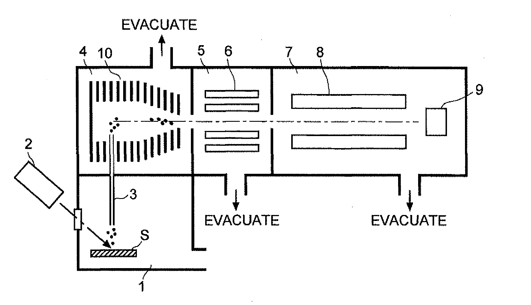
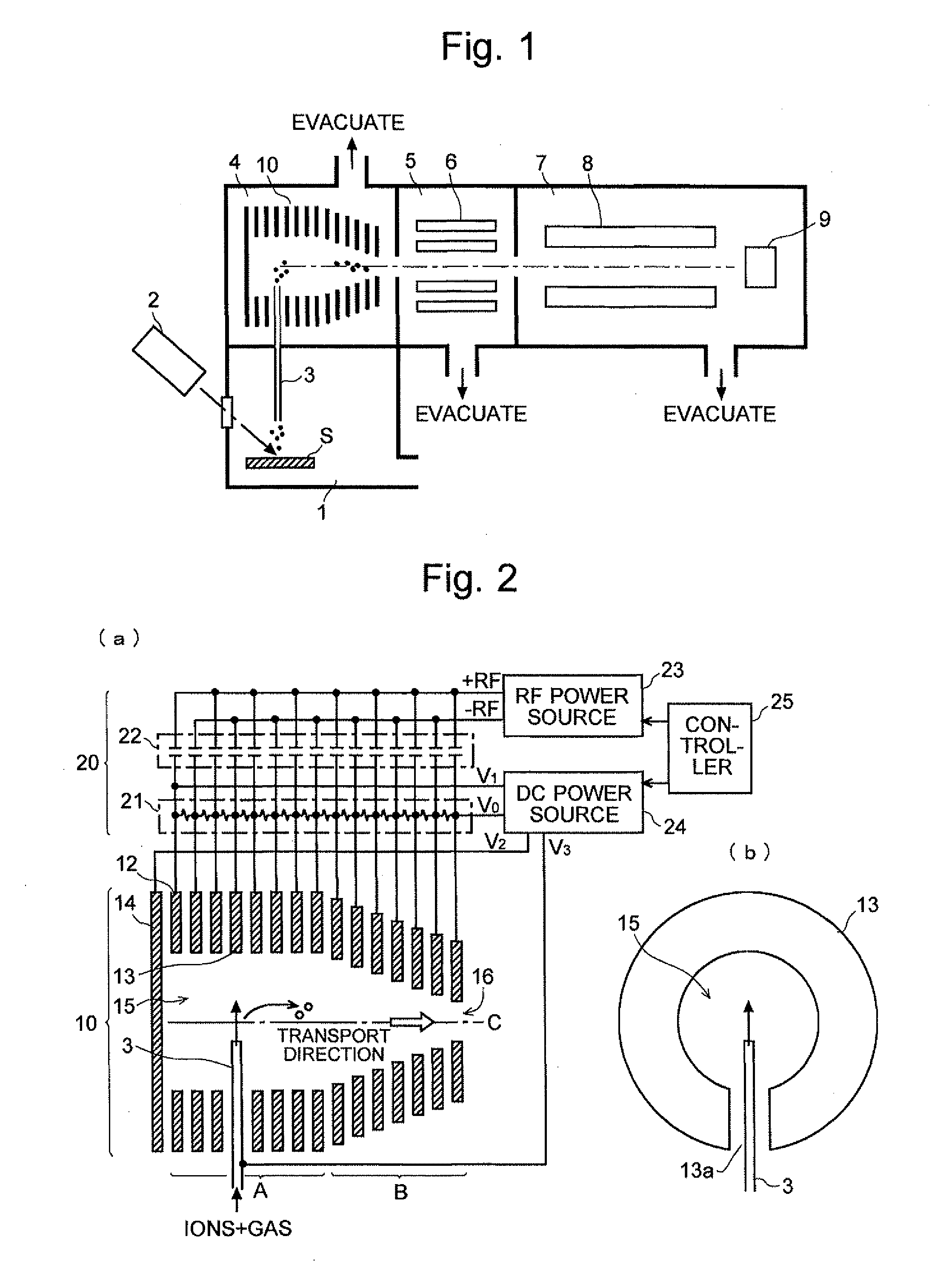
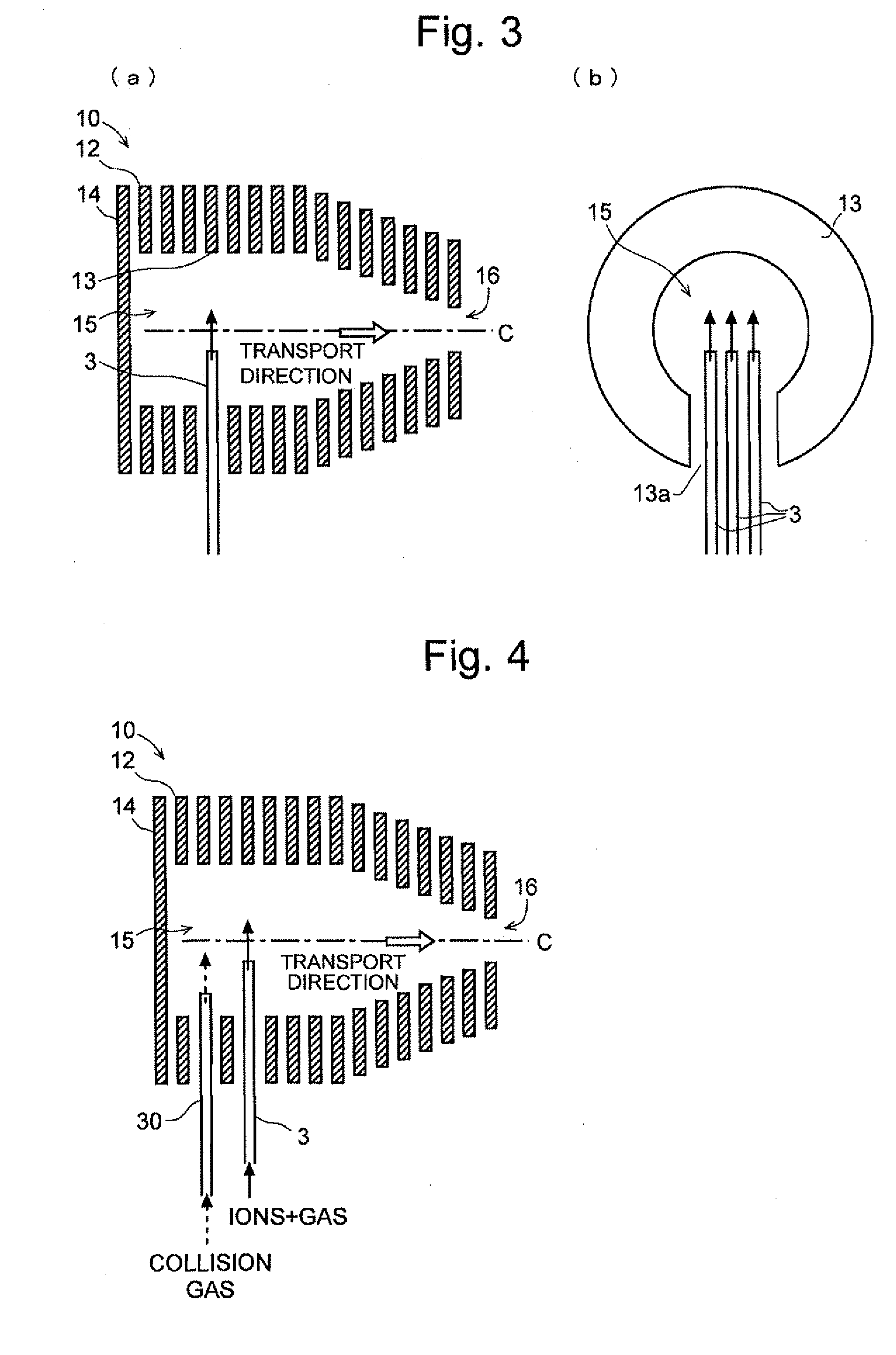
[0039]FIG. 1 is a schematic configuration diagram of an AP-MALDI mass spectrometer according to the first embodiment, and FIG. 2 is a configuration diagram of the ion-transport optical system in this mass spectrometer.

[0040]The present mass spectrometer has the configuration of a multi-stage differential pumping system including an ionization chamber 1 at approximately atmospheric pressure, a high vacuum chamber 7 evacuated with a high-performance vacuum pump (turbo molecular pump, which is not shown), and two intermediate vacuum chambers 4 and 5 provided between the aforementioned chambers 1 and 7. In the ionization chamber 1, a sample S containing a sample component to be analyzed is irradiated with a laser beam from a laser source 2, whereby the sample component is ionized. The first intermediate vacuum chamber 4 cont...

second embodiment

[0058]Another embodiment (second embodiment) of the mass spectrometer according to the present invention is hereinafter described with reference to the attached drawings.

[0059]FIG. 7 is a schematic configuration diagram of an ICP mass spectrometer according to the second embodiment, and FIG. 8 is a configuration diagram of the ion-transport system in the present mass spectrometer. The same components as used in the mass spectrometer and the ion-transport optical system of the first embodiment are denoted by the same numerals, and detailed descriptions of such components will be omitted.

[0060]In the present mass spectrometer, a sampling cone 41 is provided between the ionization chamber 1 and the first intermediate vacuum chamber 4. A micro-sized orifice 42 is bored at the top of the sampling cone 41, through which ions can be injected into the ring-electrode inner space of the electrode unit 10. For this purpose, a number of ring electrodes 17 located in the nearer half of the elect...


PUM


Abstract

A technique for improving the efficiency of injecting ions into the electrode unit of a funnel structure having high ion-transport efficiency is provided to improve the overall ion-transport efficiency. From an ionization chamber 1 for ionizing a sample under atmospheric pressure, ions are injected through a straight capillary pipe 3 into the inner space of the electrode unit 10 of a funnel structure composed of ring electrodes in a first intermediate vacuum chamber 4. The space for setting the capillary pipe 3 is formed by replacing one or more ring electrodes with C-shaped electrodes whose circumference portion is partially removed. Each C-shaped electrode is arranged so that the ions will be injected perpendicularly to the ion-transport direction. The injected ions lose energy due to collision cooling, become converged onto the ion-beam axis C due to the ion-confining effect of a radio-frequency electric field, and efficiently move toward the exit aperture along a potential gradient created by a direct-current electric field. The gas stream carrying the ions passes through the gaps of the ring electrodes, without increasing the gas pressure at the exit of the ring-electrode inner space and thereby deteriorating the degree of vacuum in the next stage.

Description

[0001]The present invention relates to a mass spectrometer, and more specifically to a mass spectrometer suitable for an atmospheric pressure ionization mass spectrometer in which a sample is ionized under approximately atmospheric pressure and subjected to mass analysis.BACKGROUND OF THE INVENTION[0002]An atmospheric pressure ionization mass spectrometer, which uses an ion source for ionizing ions under approximately atmospheric pressure by an appropriate ionization method, such as electrospray ionization (ESI), atmospheric chemical ionization (ACPI), inductively coupled plasma ionization (ICP) or atmospheric pressure matrix laser assisted ionization (AP-MALDI), generally includes a multi-stage differential pumping system to maintain a high-vacuum atmosphere within a vacuum chamber in which a mass analyzer (e.g. a quadrupole mass filter or a time of flight mass spectrometer) is provided. In this type of mass spectrometer, it is necessary to efficiently transport ions under a low-va...

Claims


Application Information

Patent Timeline
Patent Type & Authority Applications(United States)
IPC IPC(8): H01J49/10
CPCH01J49/10H01J49/062H01J49/0404H01J49/067H01J49/066
Inventor YASUNO, MOTOHIDE
Owner SHIMADZU CORP
Why Eureka
Try Eureka