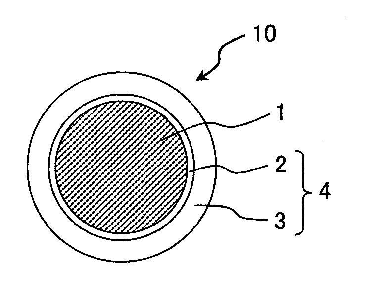
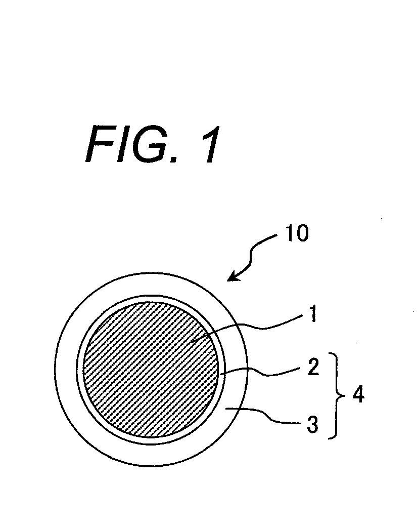
Insulated wire

a technology of insulated wires and insulating films, which is applied in the direction of insulated conductors, cables, conductors, etc., can solve the problems of partial discharge between adjacent insulated wires, adversely affecting the insulation system of the coil in electrical equipment, corrosion deterioration, etc., and achieve excellent adhesion between the layers of the insulation film and the conductor. excellent

Inactive Publication Date: 2011-08-11
HITACHI CABLE +1
View PDF3 Cites 29 Cited by
  • Summary
  • Abstract
  • Description
  • Claims
  • Application Information

AI Technical Summary

Benefits of technology

[0022]According to the present invention, it is possible to provide an insulated wire having an insulating film composed of a plurality of layers provided on the conductor, in that adhesion between the conductor and the insulation film is excellent, adhesion between layers of the insulation film is also excellent without interposing an additional layer such as an adhesion layer, and a partial-discharge start voltage is high.

Problems solved by technology

In the inverter control, a steep overvoltage (inverter surge voltage) can possibly occur, and there is concern that the increasing use of higher voltages as well as the inverter surge voltage may adversely affect the insulation system of the coil in electrical equipment.
Specifically, electric fields concentrate in the small gaps among insulated wires constituting a coil, which may result in the occurrence of partial-discharge between adjacent insulated wires (between film and film) or between the insulated wire and the ground (between film and coil core).
Partial discharge may cause corrosion deterioration (partial-discharge deterioration) of the insulation film, and with the progress of the partial-discharge deterioration, dielectric breakdown of the coil may occur.
A method of making the insulation film thick, however, has a problem in that because the thickness of the film formed by one coating and baking process is usually thin, approximately several microns, a number of repetitions of the process needs to be increased.
Consequently, production cost will increase.
On the other hand, if an insulation film is formed by simply using a fluoric polyimide resin to decrease the specific dielectric constant, there is a problem in that weak adhesion between the insulation film and a conductor tends to cause peeling, resulting in the occurrence of dielectric breakdown.
Additionally, when the insulated wire is inserted into the motor's slot, it seems that the surface of the insulation film is not damaged easily.
However, since characteristics of the resin composition of the conventional enamel layer greatly differ from those of the resin composition of the extrusion-coated resin layer, adhesion between the layers tends to become inadequate, causing inter-layer peeling or wrinkling to occur on the insulation film in severe processing conditions (e.g., where the wire is wound into a small radius), and consequently, resulting in the decrease in the partial-discharge start voltage.
However, when interposing the adhesion layer between those layers, a problem arises in that the production cost further increases.

Method used


Image

  • Insulated wire
  • Insulated wire

Examples


preparation of example 1

[0037]A copper wire having a diameter of 2 mm was used as a conductor, and a 100-μm thick first covering layer was formed on the circumference of the copper wire by means of extrusion-coating. For the resin composition of the first covering layer, an adhesive ETFE (LM-ETFE AH2000, melting point of 240° C., made by Asahi Glass Co., Ltd.) was used. For the resin composition of the second covering layer, an alloyed resin composition (hereafter, referred to as PPS-PA alloy) made by blending 10 mass % of 66 nylon (Zytel 42A made by E.I.du Pont de Nemours & Company Inc.) with a PPS resin (Torelina A900 made by Toray Industries, Inc.) was used. Next, a 20-μm thick second covering layer was formed on the circumference of the first covering layer by extrusion-coating the PPS-PA alloy, thus, an insulated wire according to Example 1 was prepared.

preparation of example 2

[0038]According to the same procedure as Example 1, a 100-μm thick adhesive ETFE was formed as a first covering layer on the circumference of a copper wire having a diameter of 2 mm. For the resin composition of the second covering layer, an alloyed resin composition (hereafter, referred to as PEEK-PA alloy) made by blending 10 mass % of 66 nylon (Zytel 42A made by E.I.du Pont de Nemours & Company Inc.) with a polyether ether ketone resin (PEEK 450G made by Victrex Manufacturing Limited) was used. Next, a 120-μm thick second covering layer was formed on the circumference of the first covering layer by extrusion-coating the PEEK-PA alloy, thus, an insulated wire according to Example 2 was prepared.

preparation of example 3

[0039]According to the same procedure as Example 1, a 30-μm thick adhesive ETFE was formed as a first covering layer on the circumference of a copper wire having a diameter of 2 mm. Next, a 120-μm thick second covering layer was formed on the circumference of the first covering layer by extrusion-coating the PPS-PA alloy, thus, an insulated wire according to Example 3 was prepared.


PUM

PropertyMeasurementUnit
storage elastic modulusaaaaaaaaaa
thicknessaaaaaaaaaa

Abstract

There is provided an insulated wire having an insulation film composed of a plurality of layers provided on a conductor, in which: the insulation film includes a first film layer and a second film layer; the first film layer is made of a first resin composition formed by graft-polymerizing a graft compound with an ethylene-tetrafluoroethylene copolymer and is provided on a circumference of the conductor; and the second film layer is made of a second resin composition being a polymer alloy made of a polyphenylene sulfide resin and a polyamide resin, or being a polymer alloy made of a polyether ether ketone resin and a polyamide resin and is provided on a circumference of the first film layer.

Description

CLAIM OF PRIORITY[0001]The present application claims priority from Japanese patent application serial no. 2010-027204 filed on Feb. 10, 2010, the content of which is hereby incorporated by reference into this application.BACKGROUND OF THE INVENTION[0002]1. Field of the Invention[0003]The present invention relates to an insulated wire having an insulation film formed by applying an insulation film paint on a surface of a conductor and baking it. Particularly, the invention relates to an insulated wire used as coil windings for electrical equipment such as motors.[0004]2. Description of the Related Art[0005]Generally, an insulated wire used for coils for electrical equipment, such as motors and transformers, is constructed such that a single layer or a plurality of layers of insulation film made by applying and baking an insulation film paint is formed on a conductor molded so as to have a cross-sectional shape (e.g. round or rectangle) to conform to the usage and shape of the coil. ...

Claims


Application Information

Patent Timeline
Patent Type & Authority Applications(United States)
IPC IPC(8): H01B7/00
CPCH01B3/301H01B3/445H01B3/441H01B3/305
Inventor ABE, TOMIYAYAMAZAKI, TAKANORIWATANABE, KIYOSHIKIKUCHI, HIDEYUKIHANADA, TAKAHIKOHINO, DAISUKE
Owner HITACHI CABLE
Why Eureka
Try Eureka