

Article with a ceramic coating and method for producing such an article using a laser
a technology of ceramic coating and laser, which is applied in the direction of heat inorganic powder coating, nuclear engineering, railway components, etc., can solve the problems of discontinuous coating, high energy consumption, and inability to form, so as to achieve high melting or softening point, low melting point, and low energy consumption.
- Summary
- Abstract
- Description
- Claims
- Application Information
AI Technical Summary
Benefits of technology
Problems solved by technology
Method used
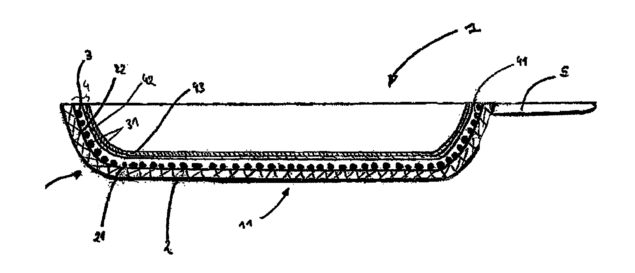
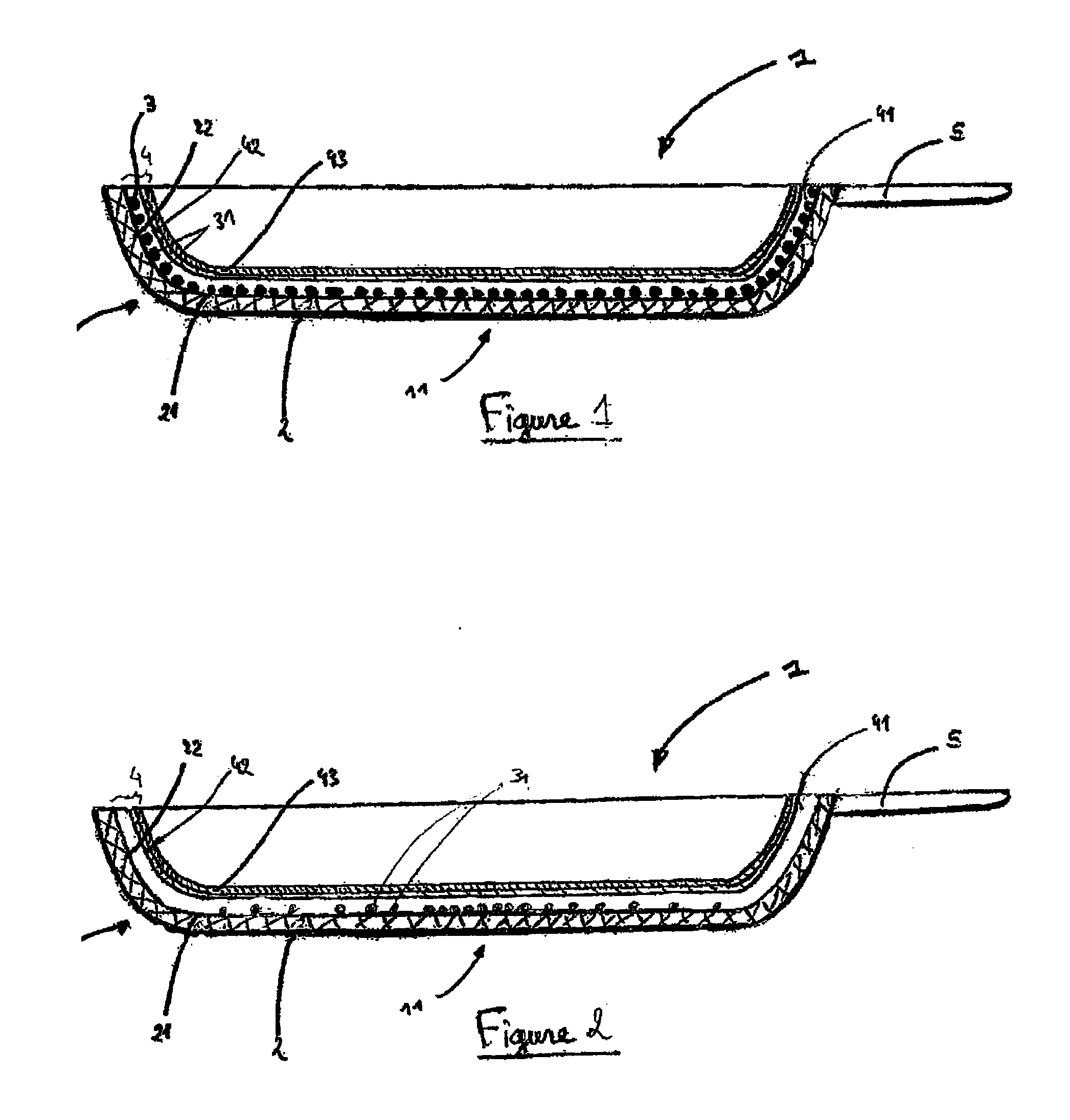
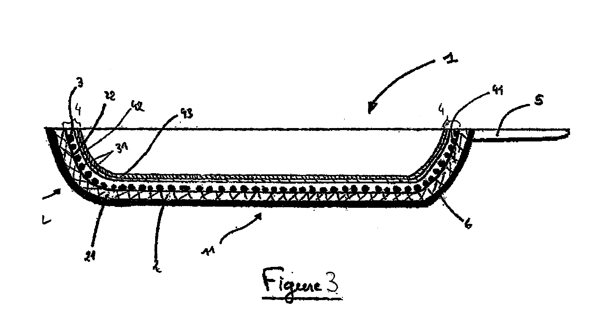
Image

Examples
example 1
[0210]Starting with an Aqueous Slip Based on “Aluminium” Enamel Frit with an Absorber, and Sintering by the Laser Route
[0211]Procedure[0212]1. An aluminium disc 300 mm in diameter is used as the substrate. This disc is degreased, then brushed to obtain a roughness Ra of 1.5 μm.[0213]2. An aqueous slip of enamel fit is prepared from “aluminium” enamel fit F1 according to the proportions given below:[0214]100 parts frit by weight[0215]60 parts water by weight[0216]1 part absorber by weight[0217]3. Then this slip is applied to one of the faces of the substrate by pneumatic spraying under a pressure of 5 bars: the deposit obtained is discontinuous and the dry weight deposited is 1.2 g before sintering.[0218]4. For laser sintering of the enamelled deposit, a fiber laser is used operating at 4 kW and emitting at a wavelength of 1,064 nm: the laser beam scans the entire surface and frits the enamel droplets to form a discontinuous enamel layer.[0219]5. The excess, non-fritted enamel is eli...
example 2
[0282]Starting with an Aqueous Slip of “Steel Enamel Frit” with an Absorber and Sintering by the Laser Route
[0283]Procedure[0284]1. An aluminium disc 300 mm in diameter is used as a substrate. This disc is degreased, then brushed to obtain a roughness Ra of 1.5 μm.[0285]2. An aqueous enamel frit slip prepared from F2 “steel” enamel frit using the proportions shown below:[0286]100 parts by weight of frit[0287]60 parts by weight of water, and[0288]1 part by weight of absorber.[0289]3. Then this slip is applied to one of the faces of the substrate by pneumatic spraying under 5 bars pressure: the deposit obtained is discontinuous and the dry weight deposited is 1.2 g before sintering.[0290]4. For laser sintering the enamelled deposit a fiber laser is used, operating at 5 kW and emitting at a wavelength of 1,064 nm: the laser beam scans the entire surface and fits the droplets of enamel to form a discontinuous enamel layer.[0291]5. The excess, non-fitted enamel is eliminated by brushing ...
control example c2
[0302]Starting with an Aqueous Slip of “Steel” Enamel Frit Without an Absorber, and Sintering by Oven Firing at 560° C.
[0303]Procedure[0304]1. An aluminium disc 300 mm in diameter is used as a substrate. This disc is degreased, then brushed to obtain a roughness Ra of 1.5 μm.[0305]2. An aqueous enamel slip frit is prepared from F2 “steel” enamel frit using the proportions given below:[0306]100 parts by weight of frit, and[0307]60 parts by weight of water.[0308]3. This slip is then applied to one of the faces of the substrate by pneumatic spraying under 5 bars pressure: the deposit obtained is discontinuous and the dry weight deposited before sintering is 1.2 g.[0309]4. The discontinuous layer is fired in an oven at 560° C. for 8 minutes to harden it.
[0310]The firing temperature is insufficient for hardening the hard base, which remains in powder form with no adhesion to the substrate.
[0311]On the other hand, firing at a higher temperature, 650° C. in particular, which is a temperatu...
PUM
| Property | Measurement | Unit |
|---|---|---|
| thickness | aaaaa | aaaaa |
| thickness | aaaaa | aaaaa |
| thickness | aaaaa | aaaaa |
Abstract
Description
Claims
Application Information