Method for producing a planographic printing plate

a technology of planographic printing and printing plate, which is applied in the direction of lithography, photomechanical equipment, instruments, etc., can solve the problems of image recording layers usable for infrared laser recording generating development wastes, image defects, and precipitation to form development wastes, so as to prevent the prevent time-dependent generation of development wastes. , good developability

Inactive Publication Date: 2011-08-18
FUJIFILM CORP
View PDF8 Cites 10 Cited by
  • Summary
  • Abstract
  • Description
  • Claims
  • Application Information

AI Technical Summary

Benefits of technology

[0050]According to an aspect of the invention, there is provided a method for making a planographic printing plate, the planographic printing plate providing good developability while preventing the generation of development wastes during printing of many sheets, or preventing time-dependent generation of development wastes, even when an

Problems solved by technology

However, when the dissolved image recording layer increases in the developer, it precipitates to form development wastes (development scums).
When a considerable amount of development wastes is generated, the wastes may adhere to the planographic printing plate after plate making to cause image defects.
In particular, image recording layers usable for infrared laser recording tend to generate development wastes because they contain a photothermal converting agent having a relatively high molecular weight.
However, red

Method used


Image

  • Method for producing a planographic printing plate
  • Method for producing a planographic printing plate
  • Method for producing a planographic printing plate

Examples


synthesis example 1

[0327]In a 500-ml three-necked flask, 125 g of 4,4′-diphenylmethane diisocyanate and 67 g of 2,2-bis(hydroxymethyl)propionic acid were placed, and dissolved in 290 ml of dioxane. After adding 1 g of N,N-diethylaniline, the mixture was stirred for 6 hours under reflux by dioxane. After completion of the reaction, the reaction product was added slowly to a solution containing 4 L of water and 40 ml of acetic acid, thereby precipitating a polymer. The solid was dried in vacuo, thereby obtaining 185 g of polyurethane resin (1). The acid content thereof was 2.47 meq / g. The weight average molecular weight (polystyrene standard) was 28,000 as measured by GPC.

synthesis examples 2 to 7

[0328]Polyurethane resins (2) to (7) were synthesized in the same manner as in Synthesis Example 1, except that the starting material used in Synthesis Example 1 was replaced with the diisocyanate compounds and diol compounds shown in Table 1.

PolyurethaneresinDiisocyanateDiol(2)Diisocyanate:Diol = 1.5:1Molecular weight: 7,000(3)Diisocyanate:Diol = 1:1.2Molecular weight: 12,000(4)Diisocyanate:Diol = 1:1.1Molecular weight: 17,000(5)Disocyanate:Diol = 1:1Molecular weight: 23,000(6)Diisocyanate:Diol = 1:1Molecular weight: 25,000(7)Diisocyanate:Diol = 1:1Molecular weight: 25,000

examples a1 to a15

, and Comparative Examples A1 to A5

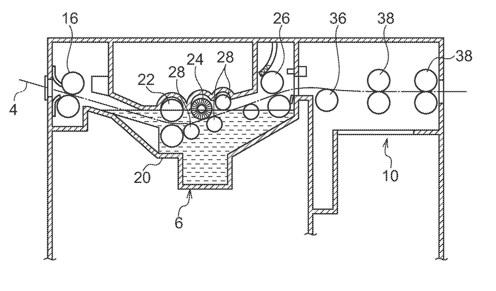
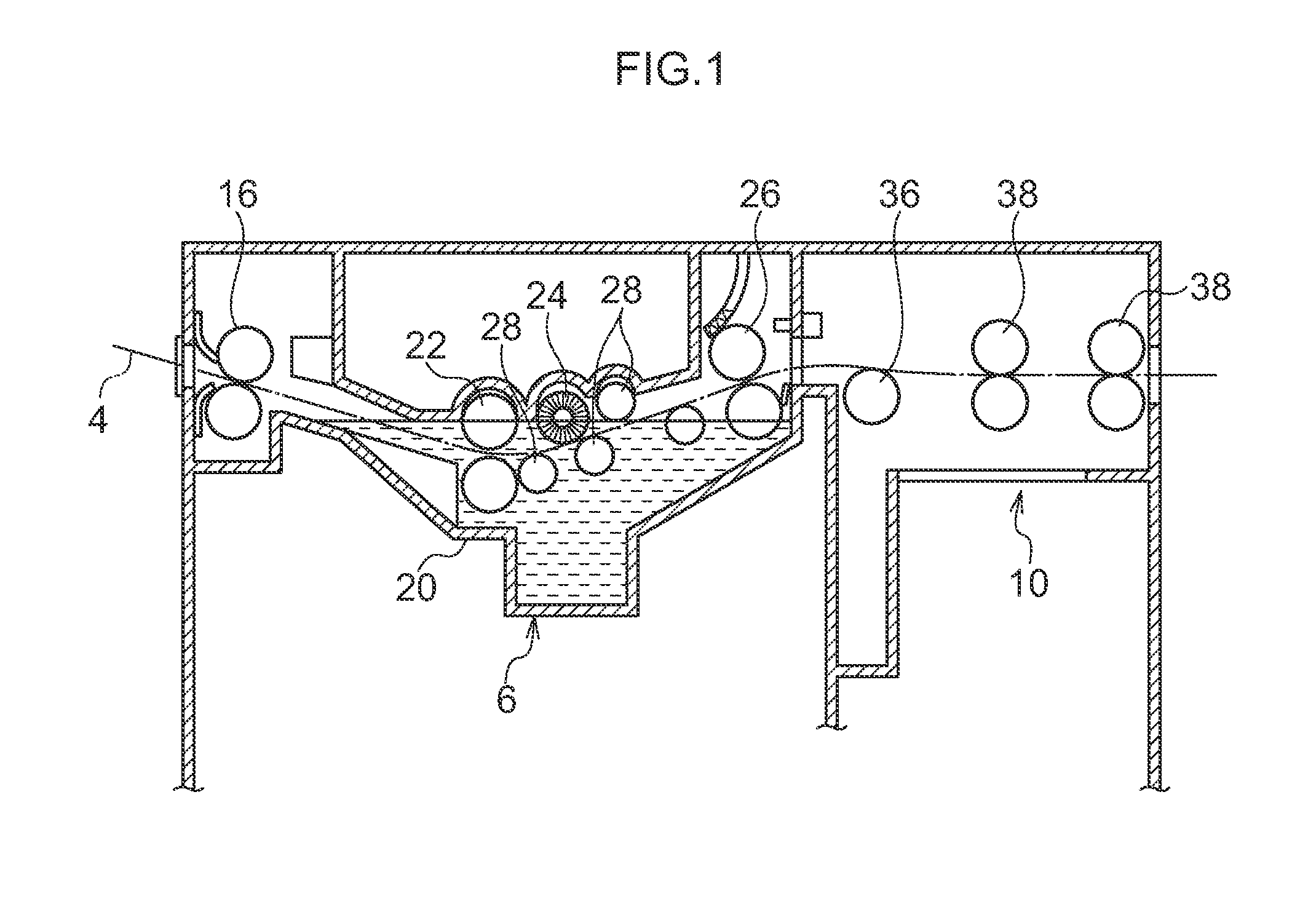
[0329]Making of Planographic Printing Plate Precursor 1 used in Example A1

[0330]Preparation of Support

[0331]An aluminum plate having a thickness of 0.24 mm (aluminum alloy composed of Si: 0.06% by mass, Fe: 0.30% by mass, Cu: 0.014% by mass, Mn: 0.001% by mass, Mg: 0.001% by mass, Zn: 0.001% by mass, and Ti: 0.03% by mass, the balance being Al and unavoidable impurities) was subjected to continuous surface treatment as described below.

[0332]Using an alternating voltage at 60 Hz, electrochemical surface-roughening treatment was continuously carried out. The electrolytic solution was a 10 g / l nitric acid aqueous solution containing 5 g / l of aluminum ions and 0.007% by mass of ammonium ions, and the solution temperature was 80° C. After water washing, the aluminum plate was subjected to etching treatment at 32° C. with a spray containing 26% by mass of sodium hydroxide and 6.5% by mass of aluminum ions, whereby the aluminum plate was dissolved at a ra...


PUM


Abstract

Provided is a method of producing a planographic printing plate, including: subjecting a planographic printing plate precursor, which has a support and a positive-working image recording layer, to image-wise exposure; and developing it using an alkaline aqueous solution which contains a specific compound and has a pH of from 8.5 to 10.8, in this order. The recording layer has: a lower layer containing a water-insoluble and alkali-soluble resin and an infrared ray absorbing agent; and an upper layer containing a water-insoluble and alkali-soluble polyurethane resin and a polyorganosiloxane. The specific compound is a nonionic or anionic surfactant, or at least one compound represented by Formula (1) or (2), wherein R11, R12, and R13 each represent an alkyl group; R14 represents an alkylene group; and R15 represents a single bond or a divalent linking group containing a hetero atom; and R21, R22, and R23 each represent an alkyl group.

Description

CROSS-REFERENCE TO RELATED APPLICATION[0001]This application claims priority under 35 USC 119 from Japanese Patent Application No. 2010-032566 filed on Feb. 17, 2010, Japanese Patent Application No. 2010-066790 filed on Mar. 23, 2010, and Japanese Patent Application No. 2010-072974 filed on Mar. 26, 2010, the disclosures of which are incorporated by reference herein.BACKGROUND OF THE INVENTION[0002]1. Field of the Invention[0003]The invention relates to a method of producing a planographic printing plate, and particularly to a method of producing a planographic printing plate providing good processability.[0004]2. Description of the Related Art[0005]In general, planographic printing plates have lipophilic image areas which receive ink during printing, and hydrophilic non-image areas which receive dampening water. Planography is a process of printing based on repellency between water and printing ink, in which lipophilic image areas of a planographic printing plate work as ink recept...

Claims


Application Information

Patent Timeline
IPC IPC(8): G03F7/20
CPCB41C1/1008G03F7/322B41C1/1016B41C2210/02B41C2210/266B41C2210/14B41C2210/22B41C2210/24B41C2210/262B41C2210/06G03F7/20G03F7/30
Inventor AOSHIMA, NORIO
Owner FUJIFILM CORP
Why Eureka
Try Eureka