Optical scanning probe assembly

a technology of optical scanning probes and assembly parts, applied in the field of optical scanning probe assembly, can solve the problems of affecting the scanning properties of the distal end, the method of guidance is far from optimal, and the resolution is limited, so as to facilitate the construction of the means for deflecting the distal end, the guide stiffness is relatively low, and the effect of low stiffness

Active Publication Date: 2011-08-18
KONINKLIJKE PHILIPS ELECTRONICS NV
View PDF11 Cites 19 Cited by
  • Summary
  • Abstract
  • Description
  • Claims
  • Application Information

AI Technical Summary

Benefits of technology

[0013]A further advantage of the invention is that it may facilitate the construction of the means for deflecting the distal end of the hollow tube, e.g. a scanning motor. Building a robust optical guide motor inside the housing with an optical guide as spring element is difficult because the stiffness of the guide is relatively low. In order to have a sufficiently rigid motor construction, the free length of the guide must be relatively short. Generally the combination of low stiffness, short bending length and small diameter requires the motor characteristics to be very sensitive to the mechanical tolerances of the guide. Moreover in case in which another type of guide, with slightly different mechanical properties, is desirable, the characteristics of the motor have to be adapted. This invention, which increases the robustness of the spring element by using a hollow tube, has the advantage of facilitating the construction of the motor by loosening its requirements.
[0014]Moreover, the improved robustness of the system improves the possible constructive parameter range and the location of the motor parts. The scanning motor is indeed located inside the housing of the probe allowing for downscaling of the system.
[0015]A further advantage of the invention may be the absence of a resonator, e.g. a tuning fork which would allow only resonant scanning. The presence of the hollow tube allows for resonant and non resonant scanning. In case of resonant scanning the hollow tube may have symmetric or asymmetric cross-sectional profile. In specific application of resonant scanning asymmetric cross-sectional profile may be advantageous because of the different resonant frequencies between the major and minor axes of the tube, which may give a favourite scanning direction.
[0016]

Problems solved by technology

Although helpful, these methods of guidance are far from optimal.
The resolution is limited and, furthermore, these imaging modalities can in most cases not discriminate between benign and malignant tissue.
However, this system has the drawback that its scanning properties strongly depends on the mechanical properties of the optical guide.
However a disadvantage of this system is that it requires a significant amount of space, due to the dimension of the tuning fork, ham

Method used


Image

  • Optical scanning probe assembly
  • Optical scanning probe assembly
  • Optical scanning probe assembly

Examples


Embodiment Construction

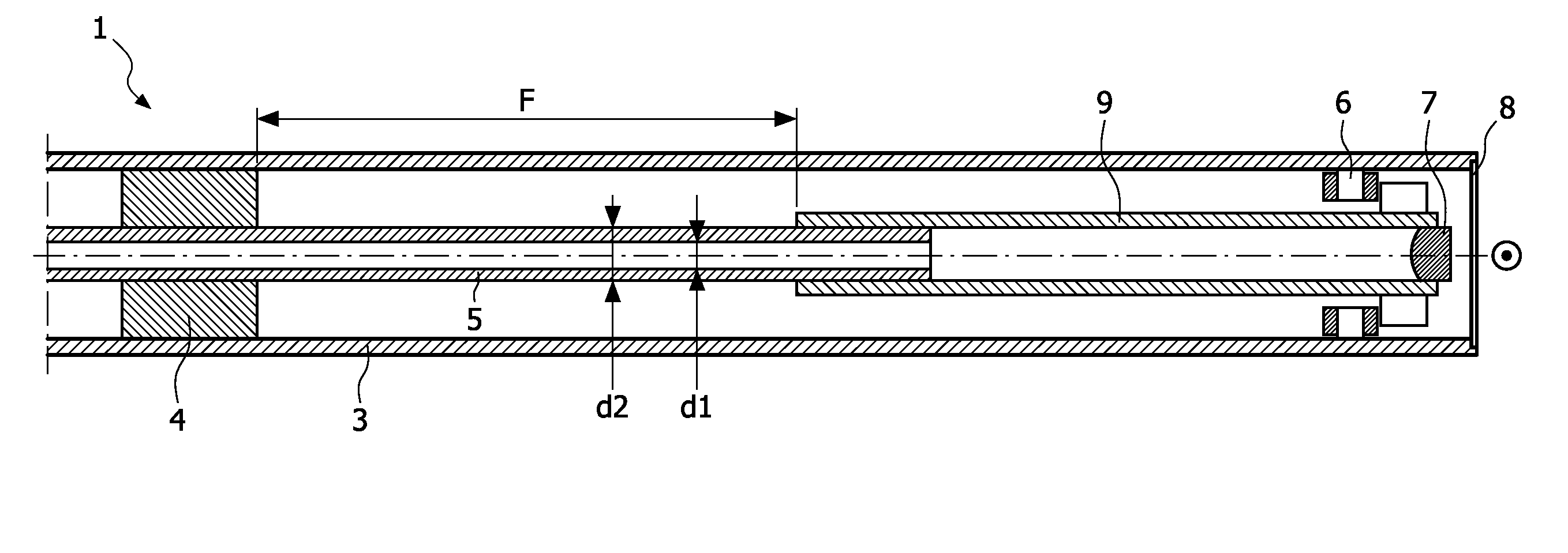
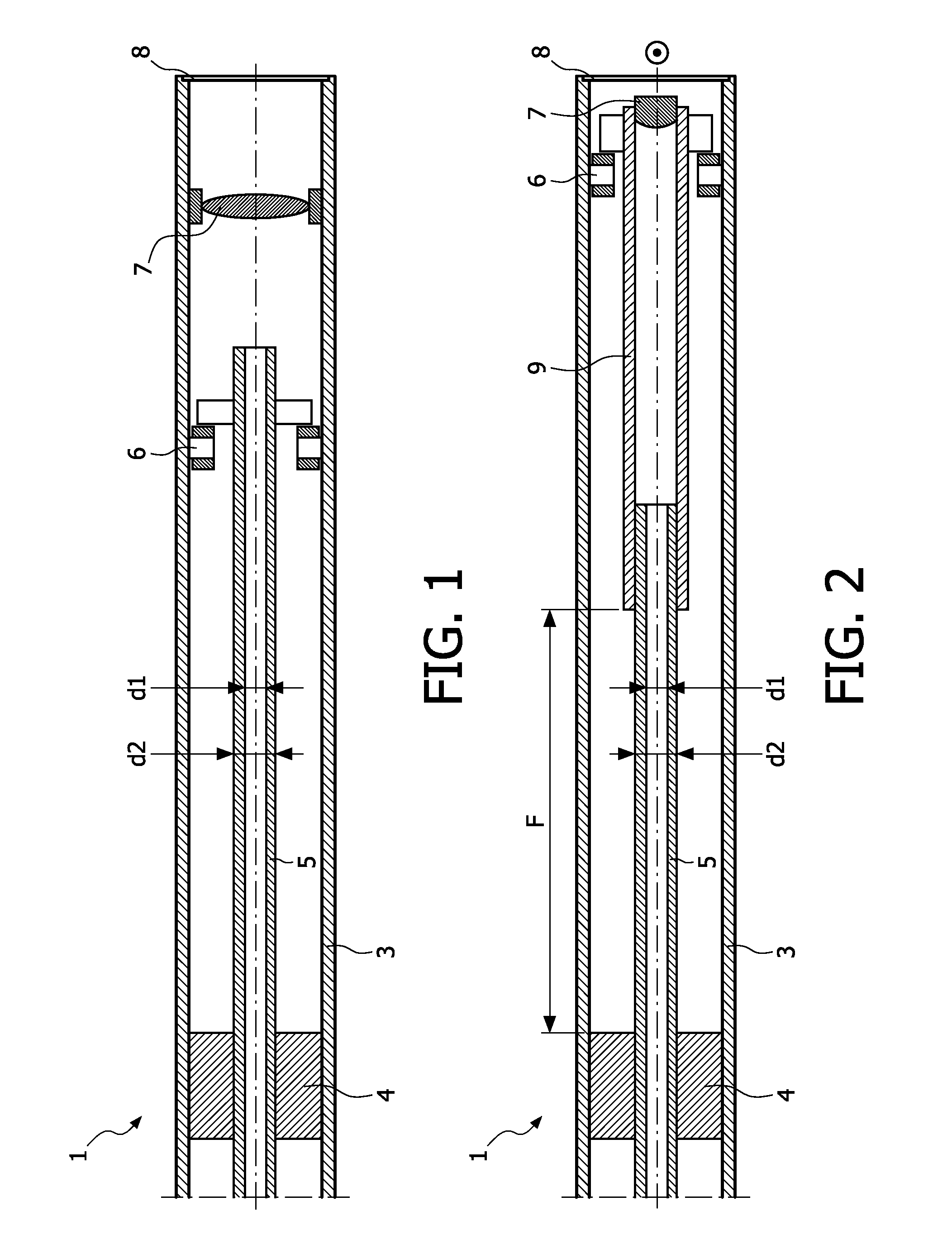
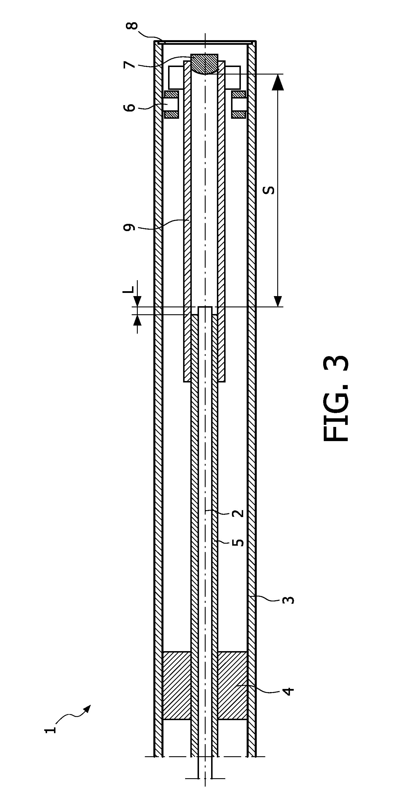
[0043]FIG. 1 is a schematic cross-sectional drawing of the scanning probe assembly 1 according to the first aspect of the present invention when the optical guide is not inserted. The optical probe 1 comprises an outer housing 3 holding through holding means 4 a hollow tube 5 with an outer diameter d2 of typically 0.8 mm and an inner diameter d1 of typically 0.5 mm. The hollow tube 5 serves as spring element for a scanning motor 6, which in this embodiment is schematically represented as an electromagnet. The lens system 7 is fixed to the housing and the focus of the system is adjusted after the insertion of the optical guide (not shown).

[0044]In the context of the present invention it is to be understood that the term “optical guide” may include, and is not limited to, optical fibers (multi-mode and single-mode), thin film optical paths, photonic crystal fibers, photonic bandgap fibers (PBG), polarization maintaining fibers, and the like. The optical probe may also comprise more th...


PUM


Abstract

The present invention relates to an optical scanning probe assembly for microscopic guide optic scanning and inspection of tissues suitable for application in, e.g. in vivo medical inspection and biopsy. The assembly comprises an outer housing (3) comprising: i) a spring element for a scanning motor, the spring element formed as a hollow tube (5) adapted to receive an optical guide, the hollow tube having mechanical stiffness larger than the optical guide to be received, ii) a lens system (7) and iii) N means for deflecting (6) the distal end of the hollow tube in directions transverse to the longitudinal extension of the hollow tube, so as to form an optical scan pattern. The optical assembly is particularly advantageous as it increases the freedom to optimize the optical and mechanical performance of the system which is defined respectively by the optical guide and by the hollow tube. The probe can be used in resonant and non-resonant scanning modes.

Description

FIELD OF THE INVENTION[0001]The present invention relates to an optical scanning probe assembly for microscopic fiber optic scanning and inspection of tissues suitable for application in, e.g. in vivo medical inspection.BACKGROUND OF THE INVENTION[0002]For correct diagnosis of various diseases, e.g. cancer, biopsies are often taken. This can either be performed via a lumen of an endoscope or via needle biopsies. In order to find the correct position where the biopsy has to be taken, various imaging modalities are used such as X-ray, Magnetic Resonance Imaging (MRI) and ultrasound. For example in most of the cases of prostate cancer the biopsy is guided by ultrasound. Although helpful, these methods of guidance are far from optimal. The resolution is limited and, furthermore, these imaging modalities can in most cases not discriminate between benign and malignant tissue.[0003]In order to improve the biopsy procedure direct inspection of the biopsy position, prior biopsy, is required....

Claims


Application Information

Patent Timeline
IPC IPC(8): A61B6/00
CPCA61B5/0062G02B26/103G02B23/2461A61B5/0084
Inventor VAN GAAL, FRANCISCUS MARTINUS ANTONIUS MARIAHENDRIKS, BERNARDUS HENDRIKUS WILHELMUSBRAUN, AUGUSTINUS LAURENTIUSHEZEMANS, CORNELIUS ANTONIUSBIERHOFF, WALTHERUS CORNELIS JOZEF
Owner KONINKLIJKE PHILIPS ELECTRONICS NV
Why Eureka
Try Eureka