Heat pipe with micro-pore tubes array and making method thereof and heat exchanging system

a technology of heat exchange system and micropore tube, which is applied in the field of heat exchange, can solve the problems of high heat conduction efficiency of pulsating heat pipes, limited application, and limited application, and achieves low heat conduction efficiency, large thermal resistance, and low resistance to inner pressur

Active Publication Date: 2011-08-25
GUANGWEI HETONG ENERGY TECH BEIJING CO LTD
View PDF21 Cites 41 Cited by
  • Summary
  • Abstract
  • Description
  • Claims
  • Application Information

AI Technical Summary

Benefits of technology

[0038]Technical effects of the invention are as follows.
[0039]The invention provides a novel heat pipe with micro tubes arrays, including a heat conductor with parallel micro tubes. The heat conductor is sealed and is filled therein with working medium for exchanging heat through phase change, i.e., the micro tube is filled with working medium, becomes a micro heat pipe and carries out heat conduction through changing phrase, such that the heat pipe effect occurs naturally. The parallel arrangement of the micro tubes may also be deemed as a group of micro tubes constituting a micro tube cluster in which micro tubes may form one or more micro heat pipe. Due to the fact that the micro tubes are arranged within a holistic structure, easy manufacturing processes, such as extrusion and stamping, may be employed to prepare the hot pipe. Therefore the invention can be widely applied. At the same time, since the micro tubes are cavities that are formed in the heat conductor not through welding or providing metal heat transfer plates, the portion of the heat conductor itself between micro tubes acts as the reinforcement ribs and there is no air cavity between micro tubes. Therefore, the problems of low heat conduction efficiency which results from large thermal resistance due to air cavities, of tendency to deformation resulting from low resistance against inner pressure, and of low welding efficiency, are solved. Therefore, the heat conductor may considerably decrease the heat resistance of the novel heat pipe, therefore considerably increase its heat conduction efficiency. Meanwhile the resistance against the pressure and reliability are enhanced. The two ends of the heat conductor are sealed, and at least one of them is provided with a sealing strip of gradually shrinking shape that is formed from cold welding, which is a unique structure resulting from the process of cold welding. On the contrary, traditional processes to seal the end usually employ hot welding to cap the end of the hot pipe, or sleeve the hot pipe into a brush and then weld the open of the brush or then melt and solder the end. This production process is rather complicated. In this invention, the unique process of employing cold welding enable to seal the end of the heat pipe in one time so as to form a novel heat pipe with a unique sealing strip of gradually shrinking shape.
[0040]By providing a reinforcement welded joint and a...

Problems solved by technology

Although the heat conduction efficiency of pulsating heat pipes is high, its application is limited due to the necessity of a temperature difference to be activated.
The general heat pipe with porous wick suffers from its complicated fabrication process and its complex maintenance, therefore its application is also limited.
However, in the former case, the air cavities existing between the pipes lead to a large heat resistance...

Method used


Image

  • Heat pipe with micro-pore tubes array and making method thereof and heat exchanging system
  • Heat pipe with micro-pore tubes array and making method thereof and heat exchanging system
  • Heat pipe with micro-pore tubes array and making method thereof and heat exchanging system

Examples


first embodiment

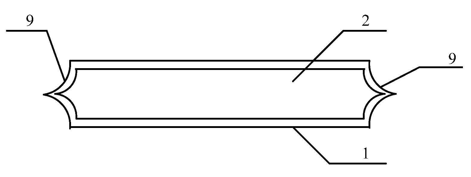
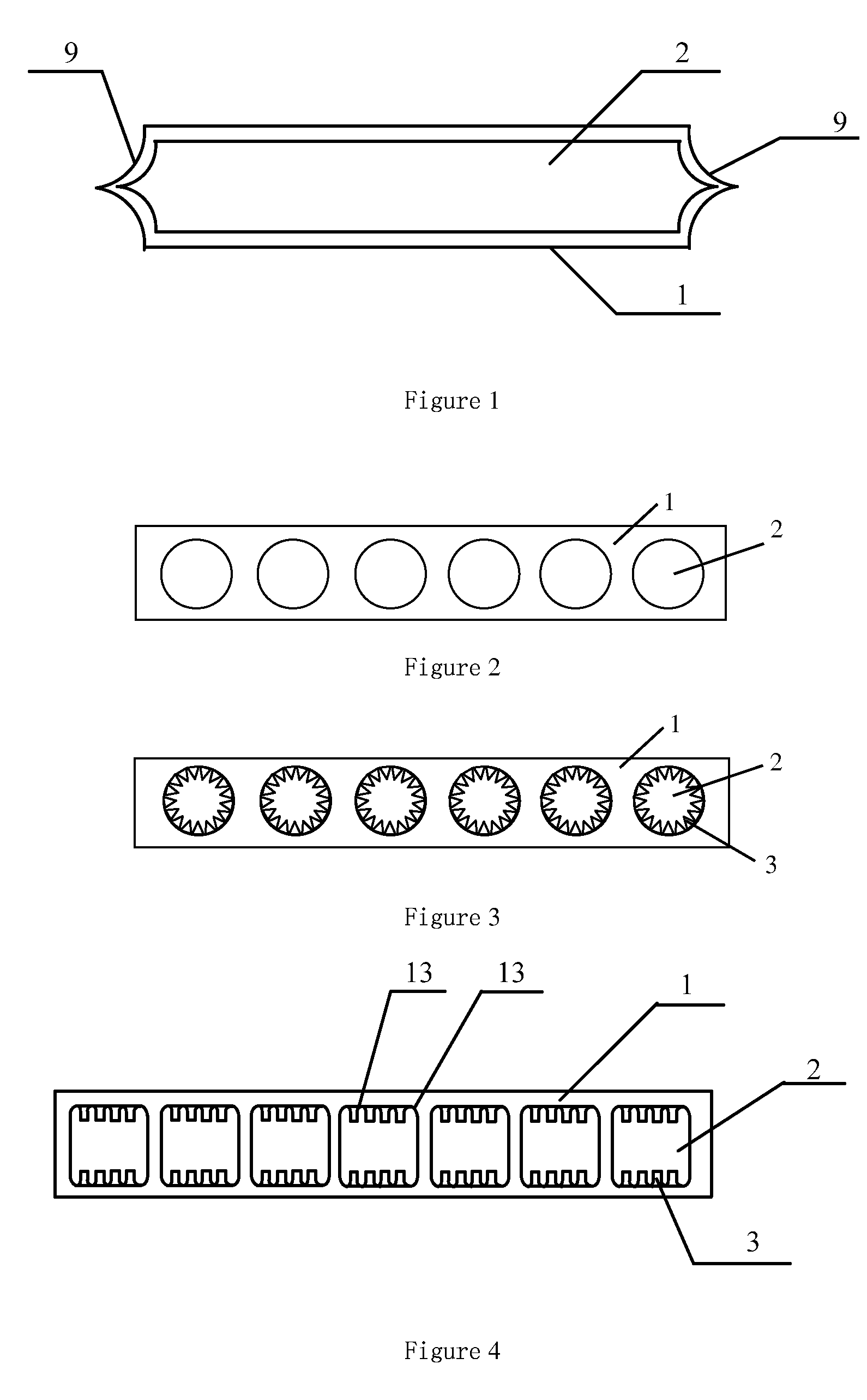
[0062]FIG. 2 is the schematic structure view of the novel heat pipe according to the invention. The heat pipe comprises a solid heat conductor 1 that may be made of metal or alloy. In this embodiment the heat conductor 1 is a plate-shaped body provided with two or more parallel micro tubes 2 which are parallel to the surface of the plate-shaped body that is wider in the cross direction. The cross sections of the micro tubes 2 are circular. The micro tubes 2 are sealed in the heat conductor 1 and are filled with liquid working medium therein so as to form micro heat pipes which conduct heat through phase-exchange and naturally result in heat pipe effect. In this embodiment, the novel heat pipe is a plate structure made of metal which is squeezed or pressed into two or more thorough holes arranged side by side. In order to improve the heat flow density and the phase-exchange ability of the novel heat pipe, the equivalent diameters or the hydraulic diameters of the micro tubes 2 may ra...

third embodiment

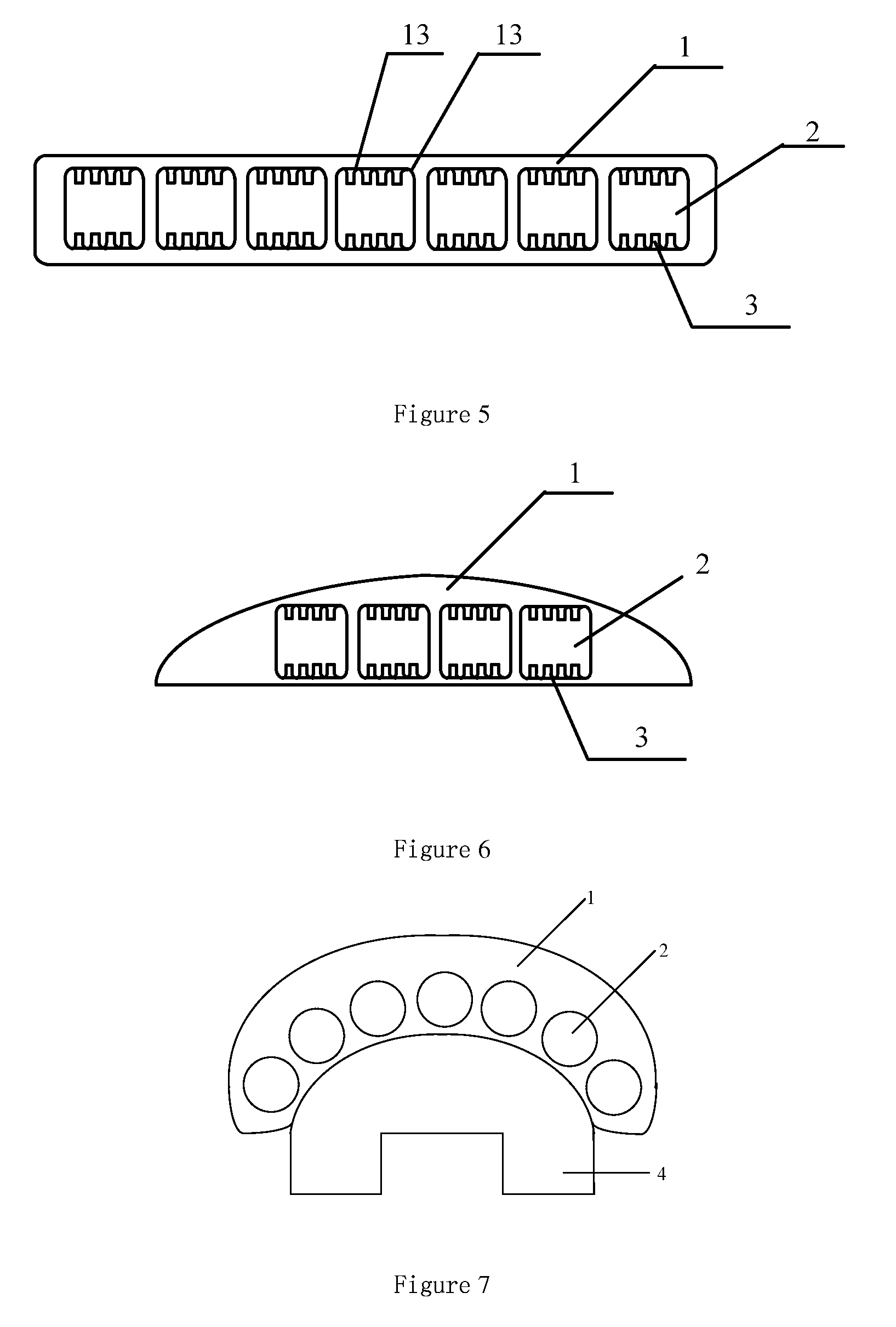
[0066]FIG. 4 is the schematic structure view of the novel heat pipe according to the invention. In this embodiment, the cross section of the micro tube 2 is rectangle. Nevertheless, the shape of the cross section may be other polygons (such as triangular or square), or ellipse, or any other geometrical shapes that would not lead to stress concentration. In case of polygons, the vertices should be chamfered so as to form a rounded corner with a certain curvature, such as the rounded corner 13 in vertex of the rectangle as shown in FIG. 4. In this embodiment, the equivalent diameters or the hydraulic diameters of the micro tubes may be set as 0.1 mm to 3.5 mm, the opposite inner walls of each micro tube 2 of rectangle shape along the vertical direction are provided with the micro-fins 3 made of heat conduction material, or with micro grooves extending in the length direction of the micro tube 2. The micro-fins 3 which are adjacent along the length direction of the novel heat pipe cons...

sixth embodiment

[0068]FIG. 7 is the schematic structure view of the novel heat pipe according to the invention. The surface of the device 4 to be cooled is a curved surface. The micro tubes 2 are arranged along the surface at which the heat conductor 1 tightly contacts with the surface of the device 4 to be cooled, such that the heat conductor 1 can contact with the surface of device 4 to be cooled tightly and thus form a heat-exchange surface. Furthermore, the micro tubes 2 are arranged in layers near the heat-exchange surface, and the heat conductor 1 can contact with the surface of the device 4 to be cooled in a large area, so the equivalent heat resistance is very small and the heat-exchange efficiency is improved.


PUM

PropertyMeasurementUnit
Diameteraaaaaaaaaa
Diameteraaaaaaaaaa
Diameteraaaaaaaaaa

Abstract

A heat pipe with micro tubes (2), comprised of a solid heat conductor (1) provided therein with two or more parallel micro tubes (2), the micro tubes being filled therein with working medium which exchanges heat through phrase change; and the two ends of the heat conductor (1) are sealed and at least one of them is provided with a sealing strip of gradually shrinking shape that is formed from cold welding. A manufacturing process for the heat pipe and a heat-exchange system comprised of the heat pipe.

Description

TECHNICAL FIELD[0001]The invention relates to the field of heat exchanging, particularly relates to a novel heat pipe which is used for heat conduction via phase-change and includes micro heat tube arrays, the manufacturing process therefor, and a novel heat-exchange system employing the novel heat pipe.BACKGROUND ART[0002]Compared with natural convection and forced convection manners, the heat exchangers that function in the phase-change principle are widely used in industries due to high heat conduction efficiency. The most typical phase-changer of this category is the heat exchanger using heat pipes. The main heat conduction mechanism of heat pipes is evaporation and condensation, which have a high heat conduction capacity, a desirable temperature controlling ability and a high heat conduction efficiency. Although the heat conduction efficiency of pulsating heat pipes is high, its application is limited due to the necessity of a temperature difference to be activated. The general...

Claims


Application Information

Patent Timeline
IPC IPC(8): F28D15/04B21D53/02F24S10/95
CPCF28D15/046H01L23/427B23P15/26F24J2/32F28D15/0233F28D15/0283Y10T29/49353F28F2260/02Y02E10/44H01L2924/0002B23P2700/09H01L2924/00F28F1/022F24S10/95Y02E10/40
Inventor ZHAO, YAOHUAZHANG, KAIRONGDIAO, YANHUA
Owner GUANGWEI HETONG ENERGY TECH BEIJING CO LTD
Why Eureka
Try Eureka