

Liquid-ejecting head and liquid-ejecting apparatus
a liquid-ejecting head and liquid-ejecting technology, applied in piezoelectric/electrostrictive/magnetostrictive devices, basic electric elements, printing, etc., can solve the problem that the piezoelectric element is unlikely to be driven at low voltage, and achieve the effect of reducing the lead content and less negative impact on the environmen
- Summary
- Abstract
- Description
- Claims
- Application Information
AI Technical Summary
Benefits of technology
Problems solved by technology
Method used
Image

Examples
first embodiment
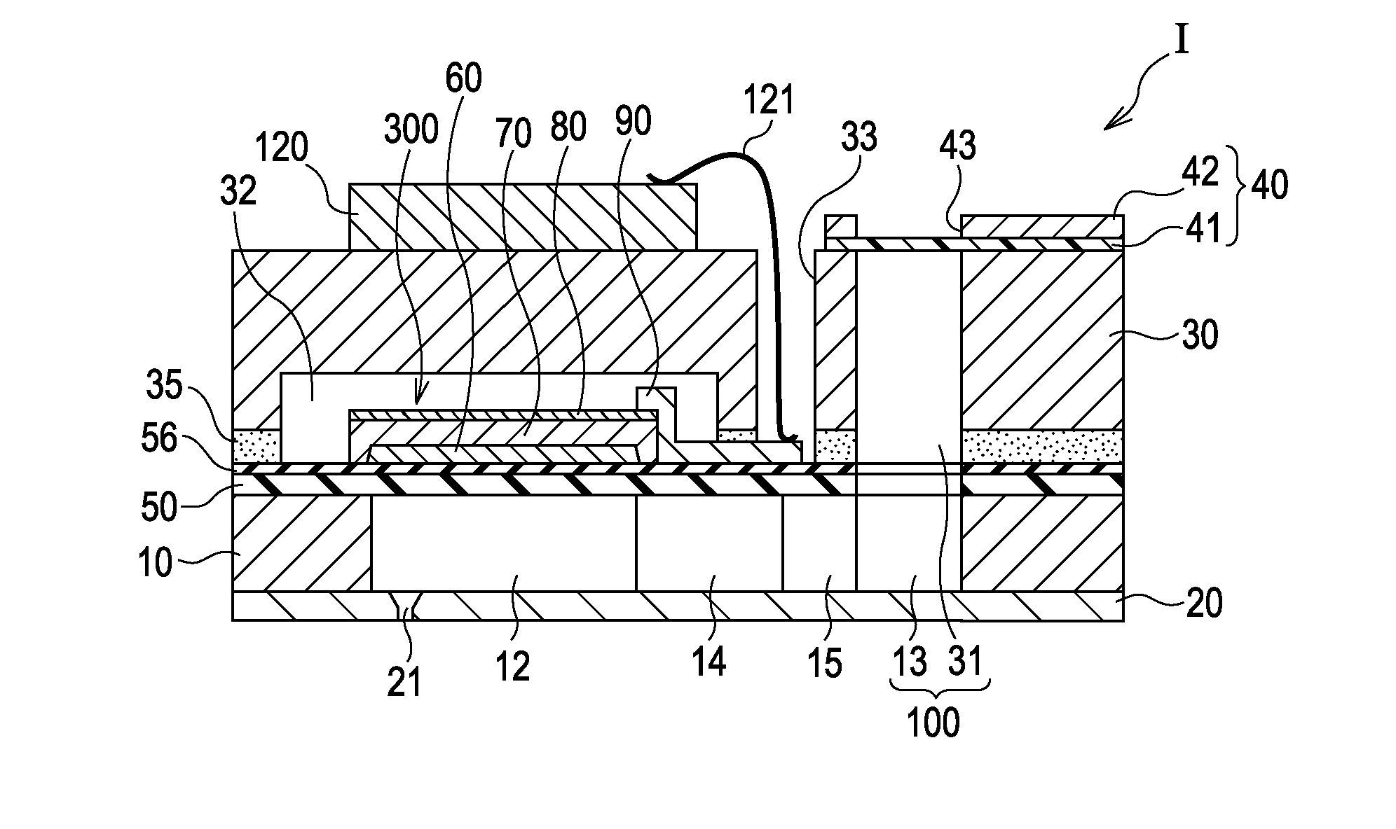
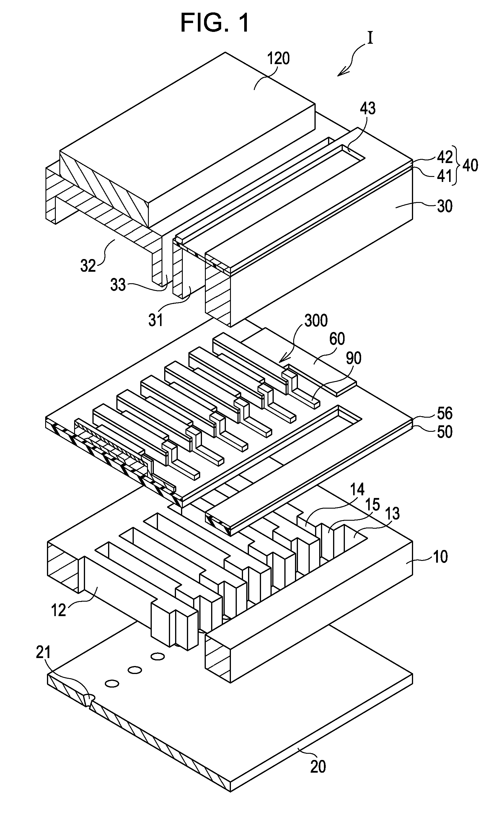
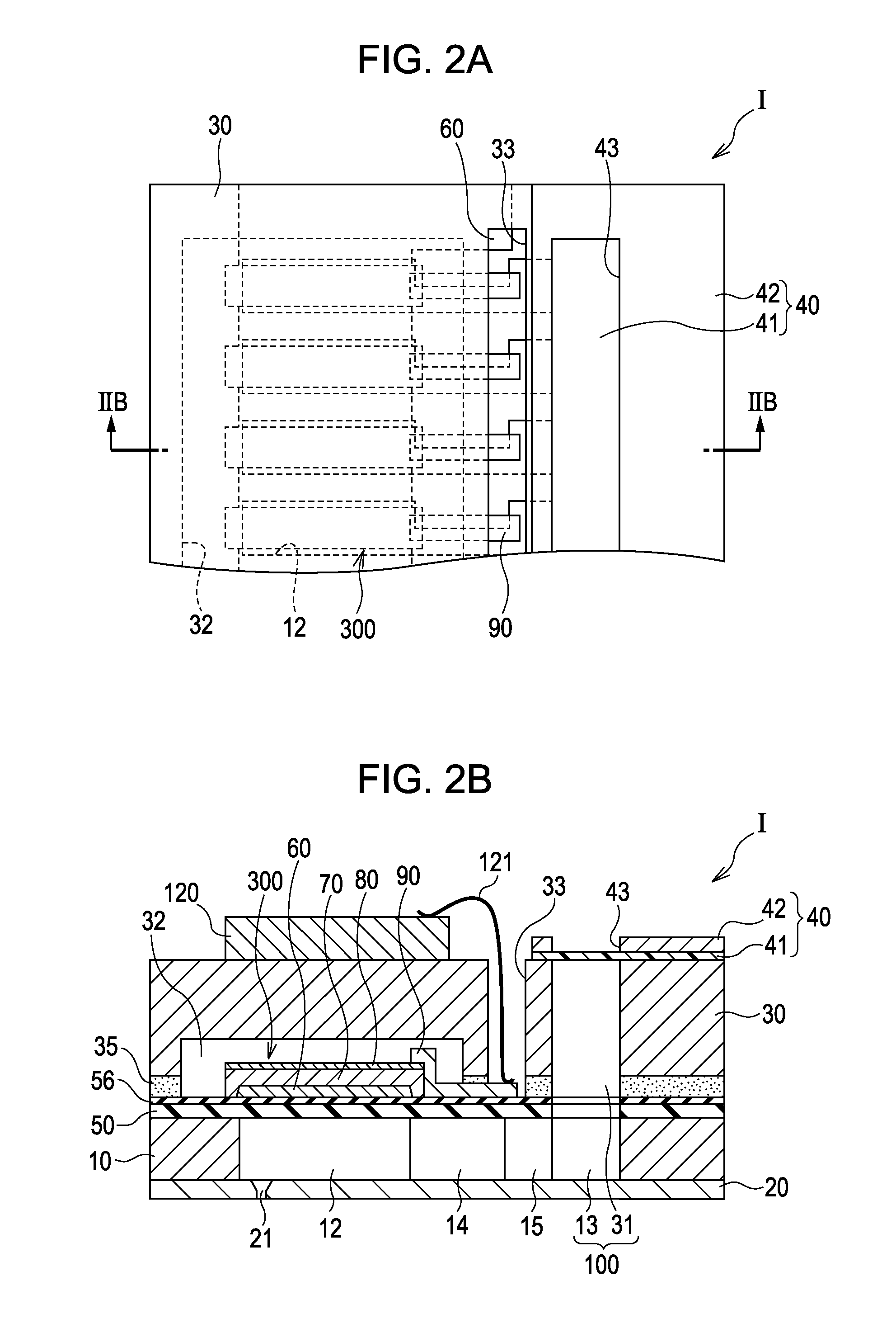
[0087]FIG. 1 is an exploded perspective view of an ink jet recording head that is an example of a liquid-ejecting head according to a first embodiment of the invention. FIG. 2A is a plan view of the ink jet recording head. FIG. 2B is a sectional view taken along the line IIB-IIB of FIG. 2A. The ink jet recording head includes a channeled substrate 10 made from a single-crystalline silicon wafer and an elastic film 50 which is made of silicon dioxide and which is disposed on a surface of the channeled substrate 10.
[0088]The channeled substrate 10 includes a plurality of pressure-generating chambers 12 arranged in the width direction thereof. A communicating portion 13 is disposed in a region of the channeled substrate 10 that is outwardly spaced from the pressure-generating chambers 12 in the longitudinal direction thereof. The communicating portion 13 is communicatively connected to the pressure-generating chambers 12 through ink supply channels 14 and communicating channels 15 each...
example 1
[0132]A silicon dioxide film was formed by the thermal oxidation of a surface portion of a silicon substrate. A titanium dioxide layer with a thickness of 40 nm was deposited on the silicon dioxide film and a (111)-oriented platinum layer with a thickness of 150 nm was deposited on the titanium dioxide layer, whereby a first electrode was formed.
[0133]A piezoelectric layer 70 was formed on the first electrode by a spin coating process. A procedure for forming the piezoelectric layer 70 was as described below. Butanol solutions each containing bismuth, potassium, sodium, or titanium were mixed at a predetermined ratio, whereby a precursor solution was prepared. The precursor solution was dripped onto the silicon substrate having the titanium dioxide layer and the first electrode and the silicon substrate was rotated at 2,500 rpm, whereby a piezoelectric precursor film was formed (a coating step). The piezoelectric precursor film was dried and degreased at 400° C. for three minutes (a...
examples 2 and 3
[0135]Piezoelectric elements 300 were prepared in substantially the same manner as that described in Example 1 except that the mixing ratio of butanol solutions each containing bismuth, potassium, sodium, or titanium was varied and complex oxides represented by Formula (1) in which x, a, and b were as shown in Table 1 were contained in piezoelectric layers 70.
TABLE 1x1 − xyabExample 10.810.1900.50.5Example 20.710.2900.50.5Example 30.610.3900.50.5Example 40.900.100.040.50.5Example 50.810.190.040.50.5Example 60.710.290.040.50.5Example 70.610.390.040.50.5Example 80.510.490.040.50.5Example 90.900.100.060.50.5Example 100.810.190.060.50.5Example 110.710.290.060.50.5Example 120.610.390.060.50.5Example 130.900.100.120.50.5Example 140.810.190.120.50.5Example 150.710.290.120.50.5Example 160.610.390.120.50.5Comparative Example 10.900.1000.50.5
PUM
| Property | Measurement | Unit |
|---|---|---|
| thickness | aaaaa | aaaaa |
| voltage | aaaaa | aaaaa |
| voltage | aaaaa | aaaaa |
Abstract
Description
Claims
Application Information