Post-Beamformer Ultrasound Compression

a post-beamformer and compression technology, applied in the field of generating ultrasound images, can solve the problems of a major challenge in the throughput of ultrasound data, and achieve the effects of efficient wavelet packet representation, high decorrelation of input samples, and optimized performan

Active Publication Date: 2011-09-15
TEXAS INSTR INC
View PDF3 Cites 19 Cited by
  • Summary
  • Abstract
  • Description
  • Claims
  • Application Information

AI Technical Summary

Benefits of technology

[0013]The example embodiments use two transforms to decorrelate the ultrasound signal in the lateral and axial directions. Wavelet packet optimization could be used online or offline to

Problems solved by technology

The high throughput of ultrasound data is a major challenge in the design of

Method used


Image

  • Post-Beamformer Ultrasound Compression
  • Post-Beamformer Ultrasound Compression
  • Post-Beamformer Ultrasound Compression

Examples


Embodiment Construction

[0020]The invention now will be described more fully hereinafter with reference to the accompanying drawings. This invention may, however, be embodied in many different forms and should not be construed as limited to the embodiments set forth herein. Rather, these embodiments are provided so that this disclosure will be thorough and complete, and will fully convey the scope of the invention to those skilled in the art. One skilled in the art may be able to use the various embodiments of the invention.

Imaging Device

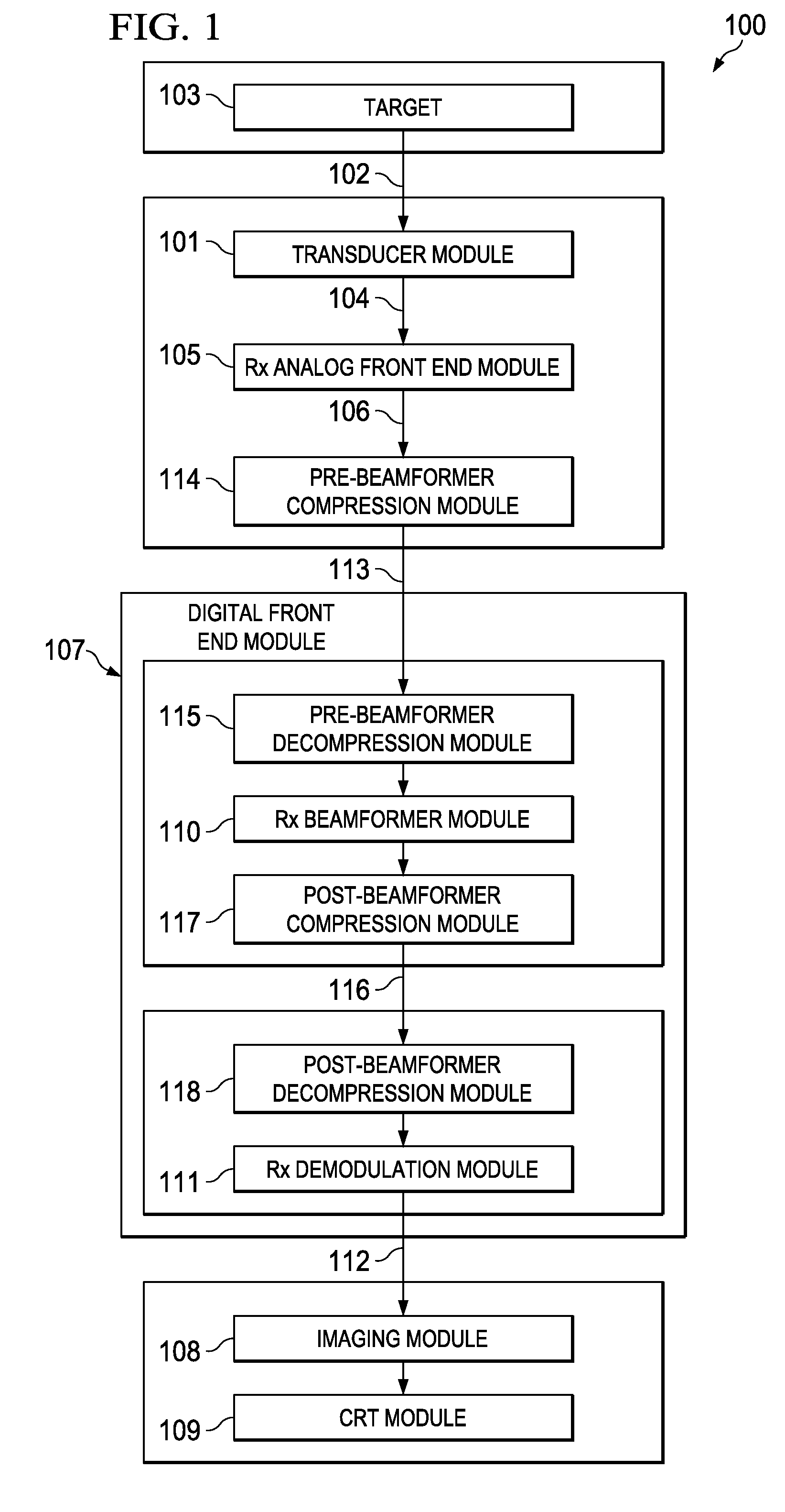
[0021]FIG. 1 is a block diagram showing the receiver portion of an imaging device 100 according to disclosed embodiments. The imaging device includes a plurality of transducers in transducer module 101, which receives echo signals 102 from a target 103 that is being imaged. The plurality of transducers operate to send a plurality of transmitted pulses to target 103 and to receive a plurality of echo pulses 102 reflected from the target 103. In one embodiment, imaging devic...


PUM


Abstract

Embodiments of the invention compress ultrasound RF data after the receiver beamformer. An efficient compression algorithm is disclosed that incorporates the use of the Discrete Cosine Transform (DCT) and the Discrete Wavelet Packet (DWP) transform, followed by quantization of the wavelet coefficients. The algorithm first processes ultrasound scanlines from the receiver beamformer using a DCT transform. In a low-power configuration, a Hadamard transform may be used instead of the DCT. The output of the DCT processing is DCT coefficients at different frequencies. An optimized wavelet packet transform is then used for each coefficient line. The wavelet filter kernels and the wavelet packet trees can be jointly optimization using a two-step optimization algorithm.

Description

CROSS-REFERENCE TO RELATED APPLICATIONS[0001]This application claims the benefit of the filing date of U.S. Provisional Patent Application No. 61 / 312,728, which is titled “Method for Post Beam-Former Ultrasound Compression” and was filed Mar. 11, 2010, the disclosure of which is hereby incorporated by reference herein in its entirety.TECHNICAL FIELD[0002]Embodiments of the invention are directed, in general, to generating ultrasound images and, more specifically, to post-beamformer compression of ultrasonic data.BACKGROUND[0003]A common type of imaging device is a pulse-echo imaging device comprising multiple transducers that transmit pulses towards a target to be imaged. The imaging device receives echoes that are reflected from the target back to the transducers. By analyzing these echoes, the imaging device creates an image of the target that reflected the pulses. An example of such a pulse-echo imaging device is an ultrasound imaging device. Beamforming is a common signal-proces...

Claims


Application Information

Patent Timeline
IPC IPC(8): G06K9/36G06K9/00
CPCG01S7/52034G01S7/003
Inventor MANSOUR, MOHAMED FAROUK
Owner TEXAS INSTR INC
Why Eureka
Try Eureka