Fast Freeform Source and Mask Co-Optimization Method

a freeform source and mask technology, applied in the field of lithographic apparatuses and processes, can solve the problems of difficult to reproduce a pattern on the wafer, large cost of making high-end mask sets, and general inability to apply opc, so as to speed up the convergence of optimization and speed up the overall convergence , the effect of improving the final resul

Active Publication Date: 2011-09-22
ASML NETHERLANDS BV
View PDF16 Cites 64 Cited by
  • Summary
  • Abstract
  • Description
  • Claims
  • Application Information

AI Technical Summary

Benefits of technology

[0020]The present invention relates to lithographic apparatuses and processes, and more particularly to tools for optimizing illumination sources and masks for use in lithographic apparatuses and processes. According to certain aspects, the present invention significantly speeds up the convergence of the optimization by allowing direct computation of gradient of a wide class of cost functions. According to other aspects, the present invention allows for simultaneous optimization of both source and mask, thereby significantly speeding the overall convergence and improving the final result. According to still further aspects, the present invention allows for free-form optimization, without the constraints required by conventional optimization techniques, and discovers the full process window entitlement absent manufacturability constraints. According to yet additional aspects, the present invention employs a method to place sub-resolution assist feature (SRAF) seeds according to free-form optimization results and grows these SRAF seeds simultaneously while performing main feature optical proximity correction (OPC) in a subsequent constrained optimization that takes into account manufacturability constraints from both source and mask sides. According to further aspects, the present invention utilizes a cost function to minimize the worst edge placement errors across process window, and a computationally friendly approximation to such a cost function.

Problems solved by technology

These rules are set by processing and design limitations.
In general, the smaller k1, the more difficult it becomes to reproduce a pattern on the wafer that resembles the shape and dimensions planned by a circuit designer in order to achieve particular electrical functionality and performance.
However, applying OPC is generally not an ‘exact science’, but an empirical, iterative process that does not always resolve all possible weaknesses on a layout.
This is driven by the enormous cost of making high-end mask sets, which run in the multi-million dollar range, as well as by the impact on turn-around time by reworking or repairing actual masks once they have been manufactured.
However, such an assumption that the source distribution is uniform in each source region is not always valid, and as a result the effectiveness of this approach suffers.
Though these methods have demonstrated some successes, they typically require multiple complicated iterations to converge.
In addition, it may be difficult to determine the appropriate / optimal values for some extra parameters, such as γ in Granik's method, which dictates the trade-off between optimizing the source for wafer image fidelity and the smoothness requirement of the source.
180) cannot perform simultaneous optimization of both source and mask.
One problem with these existing algorithms that formulate a cost function is that they require a large number of full forward optical imaging model simulations before convergence on both optimal source and mask is reached.
A clip of medium complexity would therefore take weeks or even months to optimize on latest standard PC hardware.
However, a product is generally not considered practicable unless the time required is less than about 24 hours.

Method used


Image

  • Fast Freeform Source and Mask Co-Optimization Method
  • Fast Freeform Source and Mask Co-Optimization Method
  • Fast Freeform Source and Mask Co-Optimization Method

Examples


Embodiment Construction

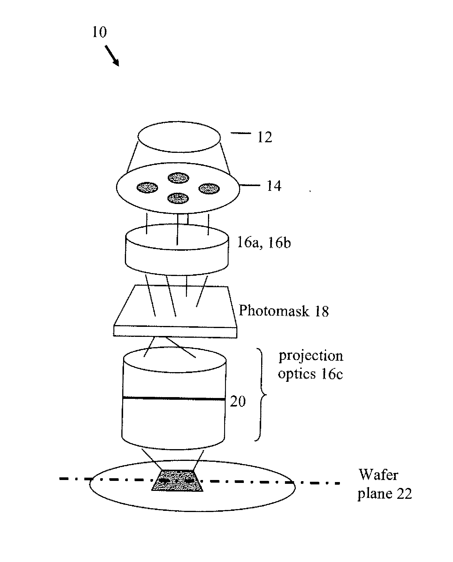
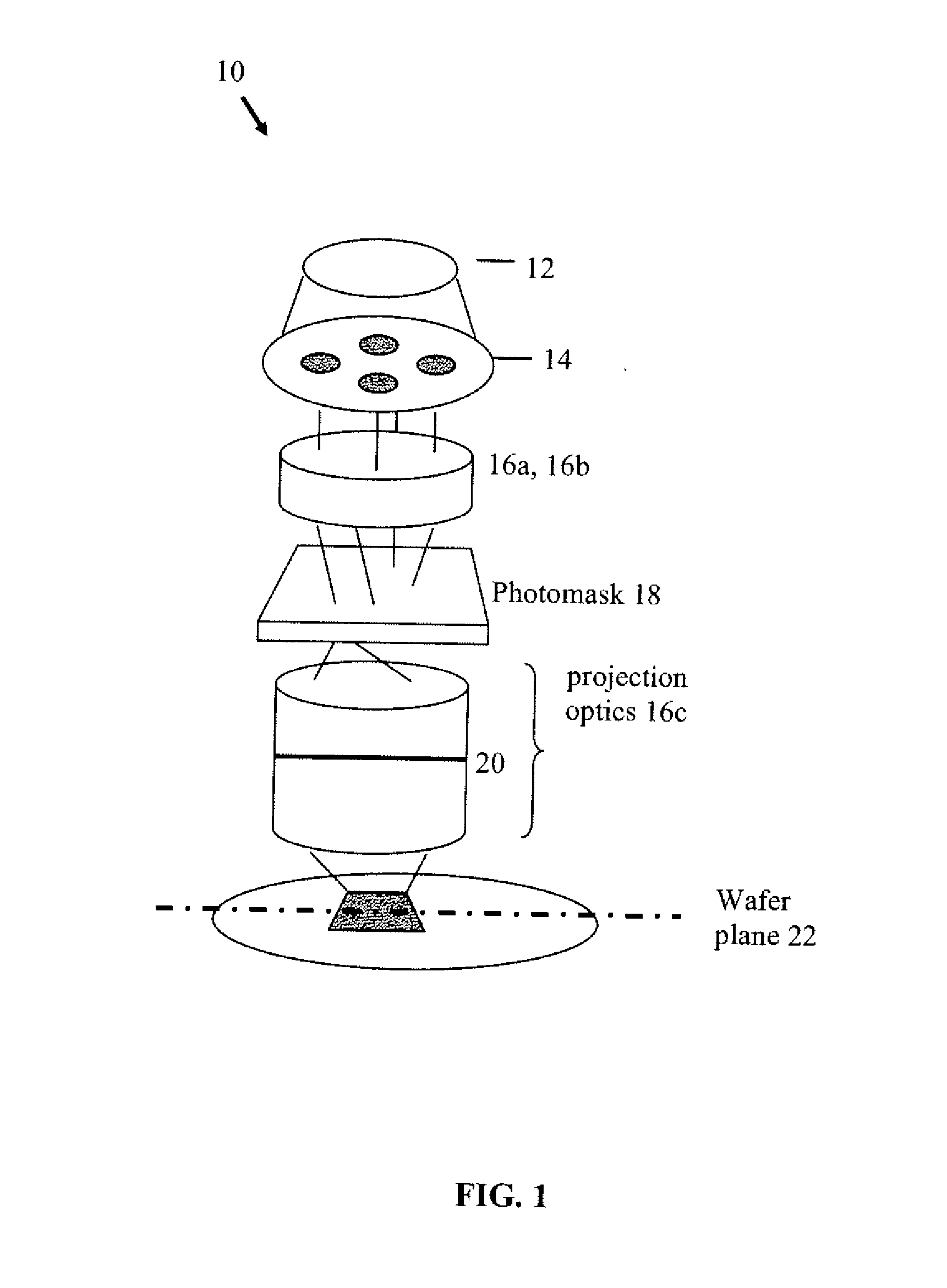
[0040]Prior to discussing the present invention, a brief discussion regarding the overall simulation and imaging process is provided. FIG. 1 illustrates an exemplary lithographic projection system 10. The major components are a light source 12, which may be a deep-ultraviolet excimer laser source, illumination optics which define the partial coherence (denoted as sigma) and which may include specific source shaping optics 14, 16a and 16b; a mask or reticle 18; and projection optics 16c that produce an image of the reticle pattern onto the wafer plane 22. An adjustable filter or aperture 20 at the pupil plane may restrict the range of beam angles that impinge on the wafer plane 22, where the largest possible angle defines the numerical aperture of the projection optics NA=sin(Θmax).

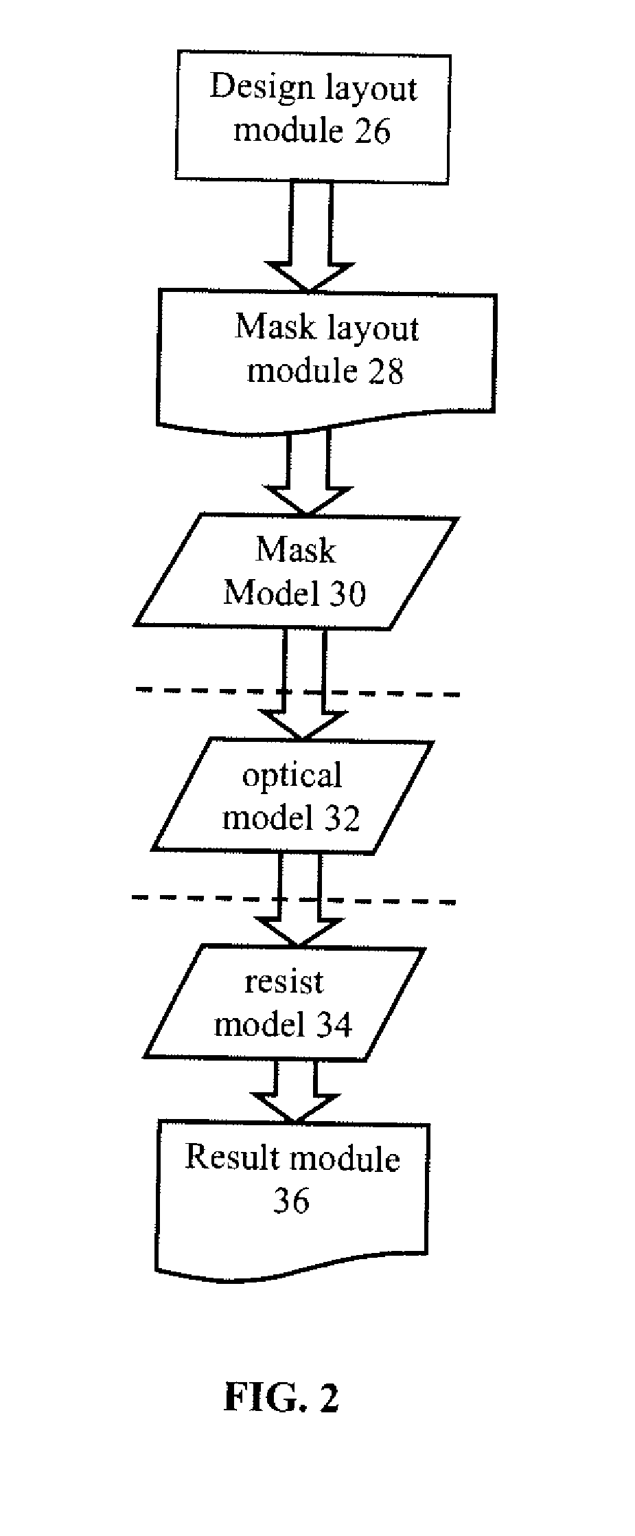
[0041]In a lithography simulation system, these major system components can be described by separate functional modules, for example, as illustrated in FIG. 2. Referring to FIG. 2, the functional modules i...


PUM


Abstract

The present invention relates to lithographic apparatuses and processes, and more particularly to tools for optimizing illumination sources and masks for use in lithographic apparatuses and processes. According to certain aspects, the present invention significantly speeds up the convergence of the optimization by allowing direct computation of gradient of the cost function. According to other aspects, the present invention allows for simultaneous optimization of both source and mask, thereby significantly speeding the overall convergence. According to still further aspects, the present invention allows for free-form optimization, without the constraints required by conventional optimization techniques.

Description

CROSS-REFERENCE TO RELATED APPLICATIONS[0001]The present application claims priority to U.S. Patent Appln. No. 61 / 116,788, filed Nov. 21, 2008, the contents of which are incorporated herein by reference in their entirety.FIELD OF THE INVENTION[0002]The present invention relates to lithographic apparatuses and processes, and more particularly to tools for optimizing illumination sources and masks for use in lithographic apparatuses and processes.BACKGROUND OF THE RELATED ART[0003]Lithographic apparatuses can be used, for example, in the manufacture of integrated circuits (ICs). In such a case, the mask may contain a circuit pattern corresponding to an individual layer of the IC, and this pattern can be imaged onto a target portion (e.g. comprising one or more dies) on a substrate (silicon wafer) that has been coated with a layer of radiation-sensitive material (resist). In general, a single wafer will contain a whole network of adjacent target portions that are successively irradiate...

Claims


Application Information

Patent Timeline
Patent Type & Authority Applications(United States)
IPC IPC(8): G06F19/00
CPCG03F1/144G03F1/36G03F7/70083G03F7/70125G06F17/5068G03F7/70441G03F7/705G03F7/70141G03F7/70258G06F30/398G06F30/39
Inventor CHEN, LUOQIYE, JUNCAO, YU
Owner ASML NETHERLANDS BV
Why Eureka
Try Eureka