Mass spectrometer

a mass spectrometer and mass spectrometer technology, applied in mass spectrometers, particle separator tube details, separation processes, etc., can solve the problems of reducing the transmission efficiency of ions and sensitivity, difficult to heat, and clogging of capillaries, so as to improve resolution, simple configuration, and high efficiency

Active Publication Date: 2011-10-20
HITACHI HIGH-TECH CORP
View PDF10 Cites 25 Cited by
  • Summary
  • Abstract
  • Description
  • Claims
  • Application Information

AI Technical Summary

Benefits of technology

[0016]According to the present invention, it is possible to introduce ions into the mass spectrometry part with a high efficiency by using a small-si

Problems solved by technology

Consequently, the transmission efficiency of ions and sensitivity decrease.
Furthermore, since it is necessary to make the conductance of the capillary between the atmospheric-pressure ion source and the high-vacuum chamber small, there is also a problem that the capillary tends to be clogged.
While a pinch valve has a small dead volume, sin

Method used


Image

  • Mass spectrometer
  • Mass spectrometer
  • Mass spectrometer

Examples


first embodiment

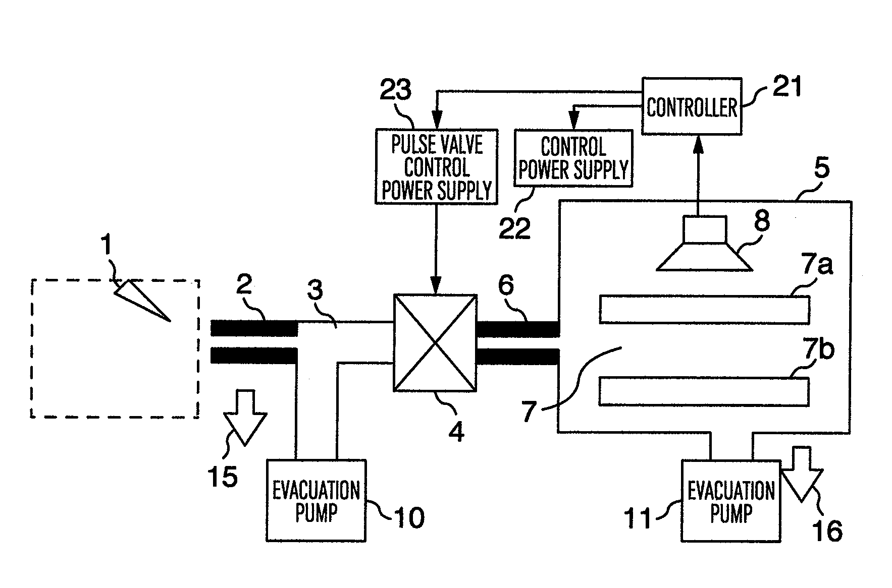
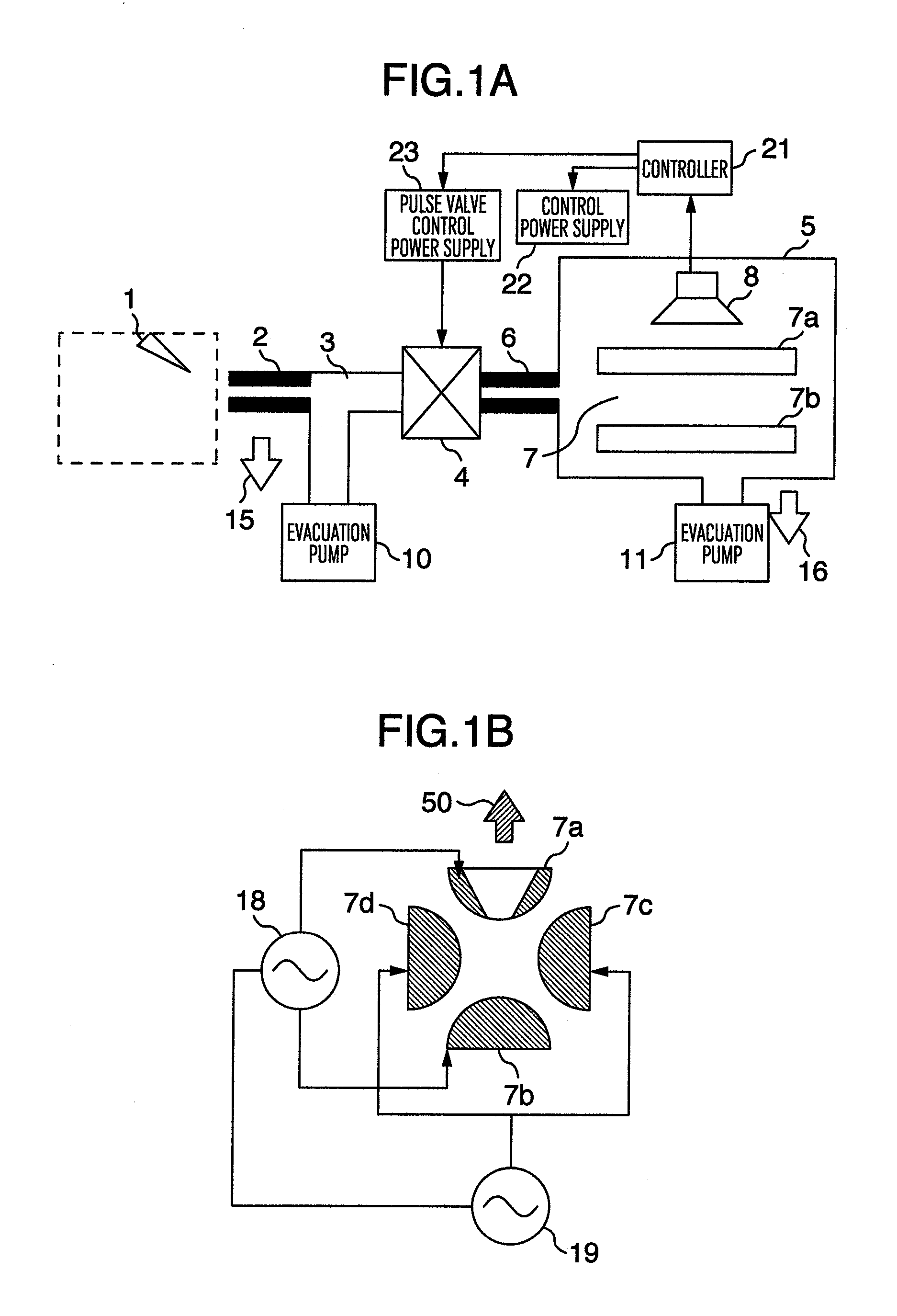
[0030]FIG. 1A is a configuration diagram of a mass spectrometer according to the present invention. Ions generated in an atmospheric-pressure ion source 1 such as an atmospheric-pressure chemical ion source or an electro-spray ion source pass through a capillary 2 together with gas and are introduced into a pre-valve evacuation region 3. The pre-valve evacuation region 3 is evacuated to approximately 100 to 10,000 Pa by an evacuation pump 10 comprising a diaphragm pump, a rotary pump, or the like. (An evacuation direction of the evacuation pump is indicated as 15.)

[0031]The pressure of the pre-valve evacuation region 3 is set to 100 to 10,000 Pa for the following reason. One of objects of the present invention is to make the pressure ratio between before and behind the valve small and to mitigate the restriction of the leak rate on the valve. For this purpose, it is necessary that the pressure before the valve is sufficiently small compared with the atmospheric pressure of 100,000 P...

second embodiment

[0050]FIGS. 6A and 6B are configuration diagrams of the pulse valve in a second embodiment according to the present invention. A configuration of the analyzer 5 and its subsequent components and a measurement sequence are the same as those in the first embodiment. In the present embodiment, however, a tri-direction globe valve suitable for fast opening / closing operation is used as the pulse valve. In a movable space, there is an opening part to a valve-inlet side piping 33, a mass-spectrometry-part side piping 34, and a vacuum-evacuation side piping 35 and passage of a sample is controlled by movement of a movable seal part 32. FIG. 6A shows the configuration when the pulse valve 4 is open; a passage between the valve-inlet side piping 33 and the vacuum-evacuation side piping 35 is blocked and the valve-inlet side piping 33 is connected to the mass-spectrometry-part side piping 34. FIG. 6B shows the configuration when the pulse valve 4 is closed; the valve-inlet side piping 33 and t...

third embodiment

[0052]FIGS. 7A and 7B are configuration diagrams of the pulse valve in a third embodiment according to the present invention. A configuration of the analyzer 5 and its subsequent components and a measurement sequence are the same as those in the first embodiment. In the present embodiment, however, a tri-direction slide valve is used as the pulse valve. In a movable space, there is an opening part to a valve-inlet side piping 33, a mass-spectrometry-part side piping 34, and a vacuum-evacuation side piping 35 and passage of a sample is controlled by sliding a movable seal part 32 having holes as illustrated. As shown in FIG. 7A, only the valve-inlet side piping 33 and the mass-spectrometry-part side piping 34 are connected together when the pulse valve 4 is open. As shown in FIG. 7B, only the valve-inlet side piping 33 and the vacuum-evacuation side piping 35 are connected together when the pulse valve 4 is closed. This way of coupling is similar to that in the second embodiment and ...


PUM


Abstract

A mass spectrometer having a resolution improved by introducing ions into a mass spectrometry part with a high efficiency is provided with a small-sized, simple configuration. The mass spectrometer includes an opening/closing mechanism provided between a sample introducing piping part for introducing a sample into the mass spectrometry part and the mass spectrometry part to conduct gas introduction intermittently and control sample passage. The mass spectrometer further includes a pump mechanism to evacuate a high pressure side of the sample introducing piping part, that is, an opposite side of the opening/closing mechanism to the mass spectrometry part to have a pressure in a range of 100 to 10,000 Pa.

Description

CLAIM OF PRIORITY[0001]The present application claims priority from Japanese patent application JP 2010-095617 filed on Apr. 19, 2010, the content of which is hereby incorporated by reference into this application.BACKGROUND OF THE INVENTION[0002]The present invention relates to a mass spectrometer.[0003]A method for introducing ions generated in an atmospheric-pressure or low-vacuum chamber into a mass spectrometry part which requires a high vacuum of 10−1 Pa or less for mass spectrometry operation in a mass spectrometer is an important technique for implementing a high sensitivity.[0004]In Analytical Chemistry, 2007, 79, 20, 7734-7739, Adam Keil, et al. a method for introducing ions supplied from an atmospheric-pressure ion source directly into the mass spectrometry part using a thin capillary provided between the atmospheric-pressure ion source and a high-vacuum chamber having the mass spectrometry part disposed therein is described. This configuration is the simplest configurati...

Claims


Application Information

Patent Timeline
IPC IPC(8): H01J49/04H01J49/26
CPCH01J49/0013H01J49/24H01J49/0495H01J49/0422
Inventor HASHIMOTO, YUICHIROHASEGAWA, HIDEKISUGIYAMA, MASUYUKIMOROKUMA, HIDETOSHI
Owner HITACHI HIGH-TECH CORP
Why Eureka
Try Eureka