Metallic Structures with Variable Properties

a technology of variable properties and metal structures, applied in the direction of electrolysis components, climate sustainability, electrolysis coatings, etc., can solve the problems of inability to easily scale, process energy intensive, and limited method practical utility

Inactive Publication Date: 2011-10-20
INTEGRAN TECH
View PDF5 Cites 77 Cited by
  • Summary
  • Abstract
  • Description
  • Claims
  • Application Information

AI Technical Summary

Benefits of technology

[0011]Coatings or layers of varying properties improve durability by minimizing surfaces and interfaces of dissimilar materials which are prone to failure. In the case of the varying the microstructure such as the grain size, grading enables the transition from a softer, tougher core to a hard, wear resistant outer surface.
[0013]Of special interest is that the variable property deposit is prepared in a single plating tank. In the past, layered structures of different composition but with uniform properties in the layer were obtained by using several plating tanks each containing a dedicated electrolyte and without varying the plating conditions. The workpiece was simply moved from one tank to the next, with repetitive washing steps in between, to effect the property change The disadvantage of this approach is increased floor space, increased capital equipment and increased processing cost due to the cost of water purification and disposal for the wash water. An added cost / risk is cross contamination particularly with complex parts which may form cups etc. entrapping electrolyte which cannot be easily removed by washing steps significantly increasing the bath maintenance and overall operating cost.

Problems solved by technology

This method is limited in its practical utility insofar as deleterious impurity contamination is frequently unavoidable, component shape flexibility is limited, the process is energy intensive, and is not readily scalable.
This method has the disadvantages that it is not applicable to pure metals, i.e., is only applicable to alloys, and that it is dependent for grading on changing Polarity Ratio, a parameter that is not directly supplied to the system.
The employment of reverse (anodic) pulses requires expensive power supplies and results in a significantly reduced plating efficiency as metal dissolution occurs during the reverse pulses.

Method used


Image

  • Metallic Structures with Variable Properties
  • Metallic Structures with Variable Properties
  • Metallic Structures with Variable Properties

Examples


working example i

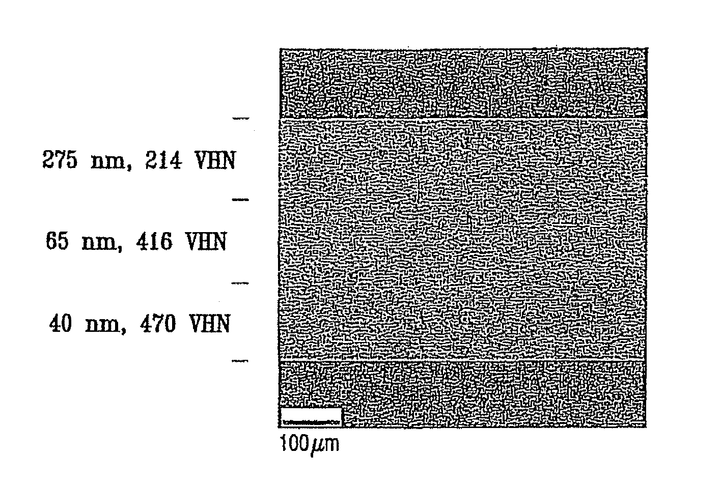
Grading of Pure Ni Electrodeposit to Grade Grain Size and Hardness in the Deposit Direction with Electrodeposition Condition Modulation

[0158]Free-standing Ni-layers with variable property and multilayered grain size were electrodeposited on a polished Ti cathode (10 cm2) in a modified Watts nickel bath (40 l tank) using grain refiners, levelers, brighteners, stress relievers and chelating agents (Integran Technologies Inc, Toronto, Ontario, Canada). Nickel “R”-rounds (Inco Ltd., Sudbury, Ontario, Canada) were used as anode material. NPA-91 wetting agent was provided by Atotech USA (Rock Hill, S.C.). The plating current was supplied by a Dynatronix (Amery, Wis., USA, Dynanet PDPR 40-100-400) pulse power supply. The electrolyte and the electroplating conditions used are indicated in Table 2. The variation in grain size of the metallic layers was achieved by modulating the electroplating conditions as set forth in Table 2. Resulting variable property structure is shown in FIG. 1. FIG. ...

working example ii

Composite Golf Shafts comprising Pure Ni Plated Layers of Different Grain Size in the Deposit Direction with Electrodeposition Condition Modulation

[0160]95 cm long, ˜1.25 cm outer diameter graphite / epoxy golf shafts (400 cm2 surface area) were coated with fine-grained Ni in a tubular tank (125 cm high, ID: 30 cm, electrolyte volume: ˜90 liter) equipped with a heater, recirculation system and a single anode basket. Golf shaft precursor tubes were mounted on a stainless steel feeder which was attached to a rotator. The modified Watts nickel bath illustrated in Table 2 of Example I was employed and precursor tubes were rotated at 15 RPM. Nickel “R”-rounds (Inco Ltd., Sudbury, Ontario, Canada) were used as anode material and the plating current was supplied by a pulse power supply (Dynatronix, Amery, Wis., USA), Before electroplating, graphite / epoxy precursor tubes were metalized with amorphous Ni-10P (Elnic 101, MacDermid Americas, Waterbury, Conn., USA) to a thickness of around 1 micr...

working example iii

Composite Golf Shafts Comprising Pure Ni Plated Layers of Mfferent Grain Size in the Denosit Direction with Electrodeposition Condition Modulation and Along its Length using Shielding

[0161]95 cm long, ˜1.25 cm outer diameter graphite / epoxy golf shafts (400 cm2 surface area) were coated with fine-grained Ni as illustrated in Example H except that the anode was shielded to impart a tapered thickness profile and grade the grain size along the surface of the shaft. Employing anode shielding and current thieves the thickness profile was adjusted to gradually decrease the thickness of the nickel coating metallic layer from 200 microns to 85 microns over the lower 30 cm of the 95 cm long tube while the Ni coating thickness of the remaining 65 cm of the tube was maintained at 85 microns. Specific to the shielding, ˜65% of the anode surface was covered with a polypropylene sheet to reduce the local current density along the aforementioned 65 cm-long section of the tube intended to have a uni...


PUM

PropertyMeasurementUnit
current densityaaaaaaaaaa
reverse current densityaaaaaaaaaa
temperatureaaaaaaaaaa

Abstract

Variable property deposit, at least partially of fine-grained metallic material, optionally containing solid particulates dispersed therein, is disclosed. The electrodeposition conditions in a single plating cell are suitably adjusted to once or repeatedly vary at least one property in the deposit direction. In one embodiment denoted multidimension grading, property variation along the length and / or width of the deposit is also provided. Variable property metallic material deposits containing at least in part a fine-grained microstructure and variable property in the deposit direction and optionally multidimensionally, provide superior overall mechanical properties compared to monolithic fine-grained (average grain size: >20 micron) or entirely amorphous metallic material deposits.

Description

CROSS-REFERENCE TO RELATED APPLICATIONS[0001]This is a continuation-in-part of U.S. patent application Ser. No. 12 / 003,224, filed Dec. 20, 2007.TECHNICAL FIELD[0002]The invention is directed to the direct current (DC) or pulsed electrodeposition of a metallic material to provide a variable property product containing, at least in part, a fine-grained metallic material with an average grain-size between 2 and 10,000 nm.BACKGROUND OF THE INVENTION[0003]Modern lightweight and durable articles require a variety of physical properties which are oftentimes not achievable with a monolithic material synthesis approach. Materials with variable properties, that is variation in a property among levels or layers, throughout the depth of the article, are described in prior art. These include parts with graded properties (such that the distinct levels or layers exhibit differing porosities, chemical compositions, grain sizes, filler amounts and / or hardness values), that is having in different lev...

Claims


Application Information

Patent Timeline
Patent Type & Authority Applications(United States)
IPC IPC(8): B32B15/04C25D5/18B32B3/30B32B5/14A63B59/00B32B15/02C23C14/34A63B65/02A63B53/12C25D5/16B32B15/01
CPCC25D1/00Y10T428/24612C25D5/08C25D5/10C25D5/14C25D5/16C25D5/18C25D15/00C25D15/02C25D21/10C25D21/12C25D21/14C25D17/008C25D5/00C23C14/3414C25D7/00C25D1/02C25D1/04C25D5/022C25D5/623C25D5/67C25D5/619C25D5/617C25D5/611Y02T50/60
Inventor TOMANTSCHGER, KLAUSHIBBARD, GLENNPALUMBO, GINOBROOKS, IAINMCCREA, JONATHANSMITH, FRED
Owner INTEGRAN TECH
Why Eureka
Try Eureka