V-Trough Photobioreactor System and Method of Use

a photobioreactor and v-trough technology, applied in biochemistry apparatus and processes, plant cultivation, horticulture, etc., can solve the problems of high device productivity, increased economic burden, and insufficient volume loss, etc., to achieve less mixing energy, increase productivity, and improve efficiency

Inactive Publication Date: 2011-10-27
HELIAE DEVMENT
View PDF3 Cites 30 Cited by
  • Summary
  • Abstract
  • Description
  • Claims
  • Application Information

AI Technical Summary

Benefits of technology

[0012]The V-trough PBR systems disclosed herein concentrate settleable material at an axis, and apply gas at the same point for mixing and keeping materials and algae in suspension. This system of agitation also serves to bring algae to the surface, where light penetration may be focused for increased productivity. The geometric shape of the V defines the axis where solids would otherwise concentrate. These V-trough PBR systems are more eff...

Problems solved by technology

Much of this imported oil is supplied by nations in politically volatile regions of the world, a fact which poses a constant threat to a stable oil supply for the United States.
Although the United States can continue to increasingly import foreign oil, global oil supplies are not infinite and importation continues to increase the United States trade deficit and create an increasing burden on the economy.
These devices have high productivity, but not high enough to make up for the loss in volume.
Other PBR systems, such as ponds, raceways or troughs are used to provide larger scale production, but these systems suffer from low productivity.
Cur...

Method used


Image

  • V-Trough Photobioreactor System and Method of Use
  • V-Trough Photobioreactor System and Method of Use
  • V-Trough Photobioreactor System and Method of Use

Examples


Embodiment Construction

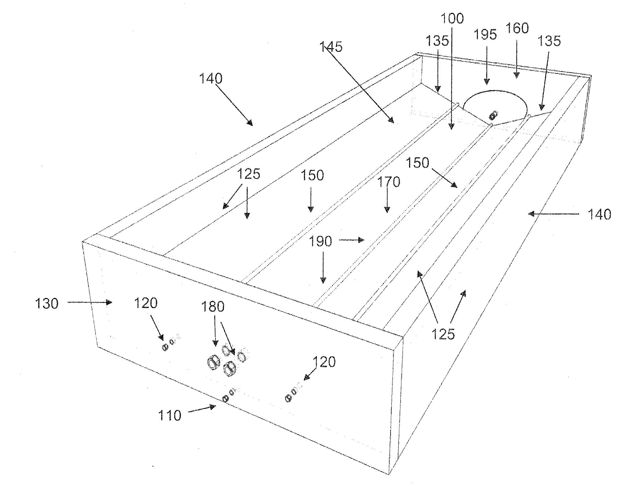
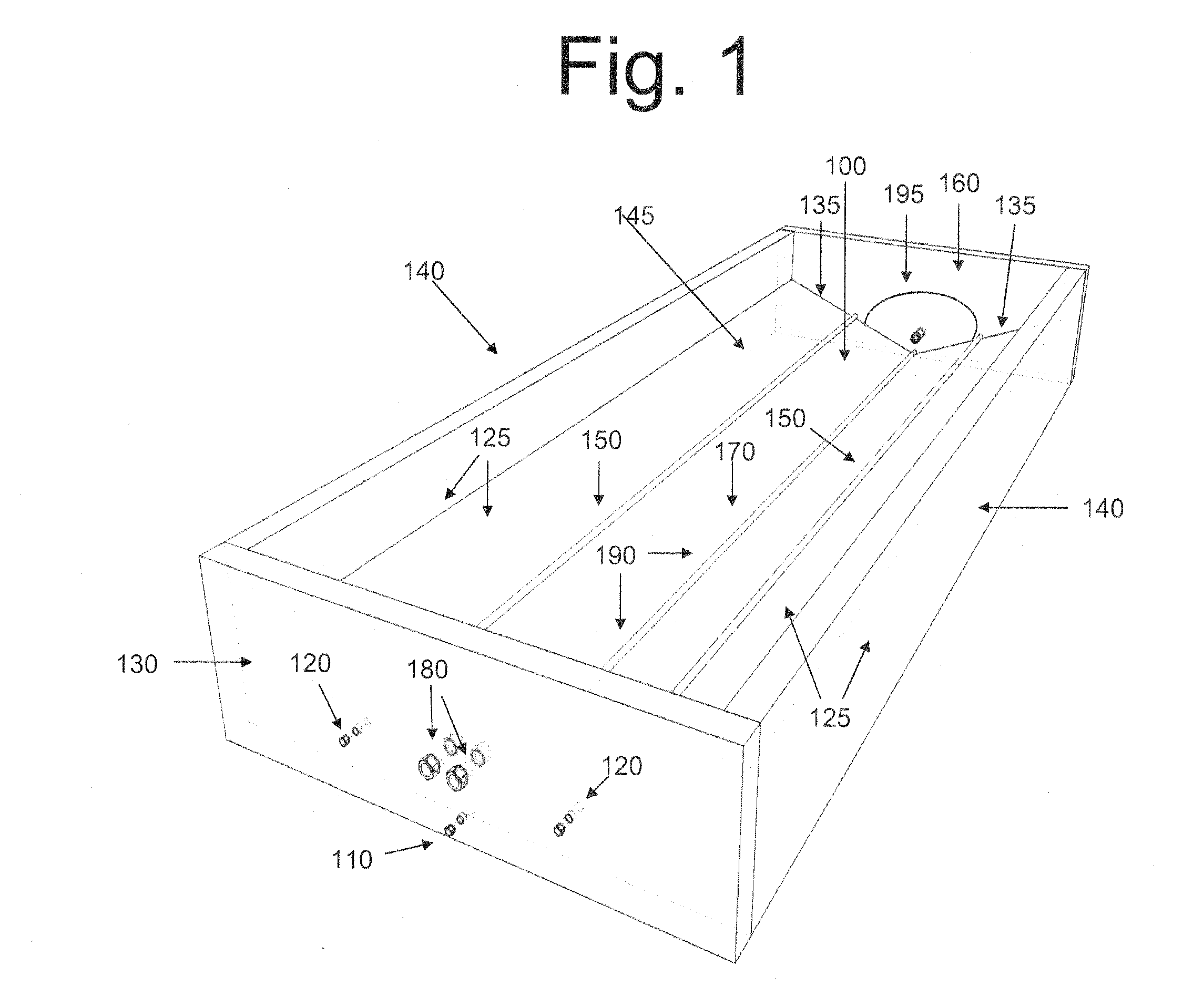
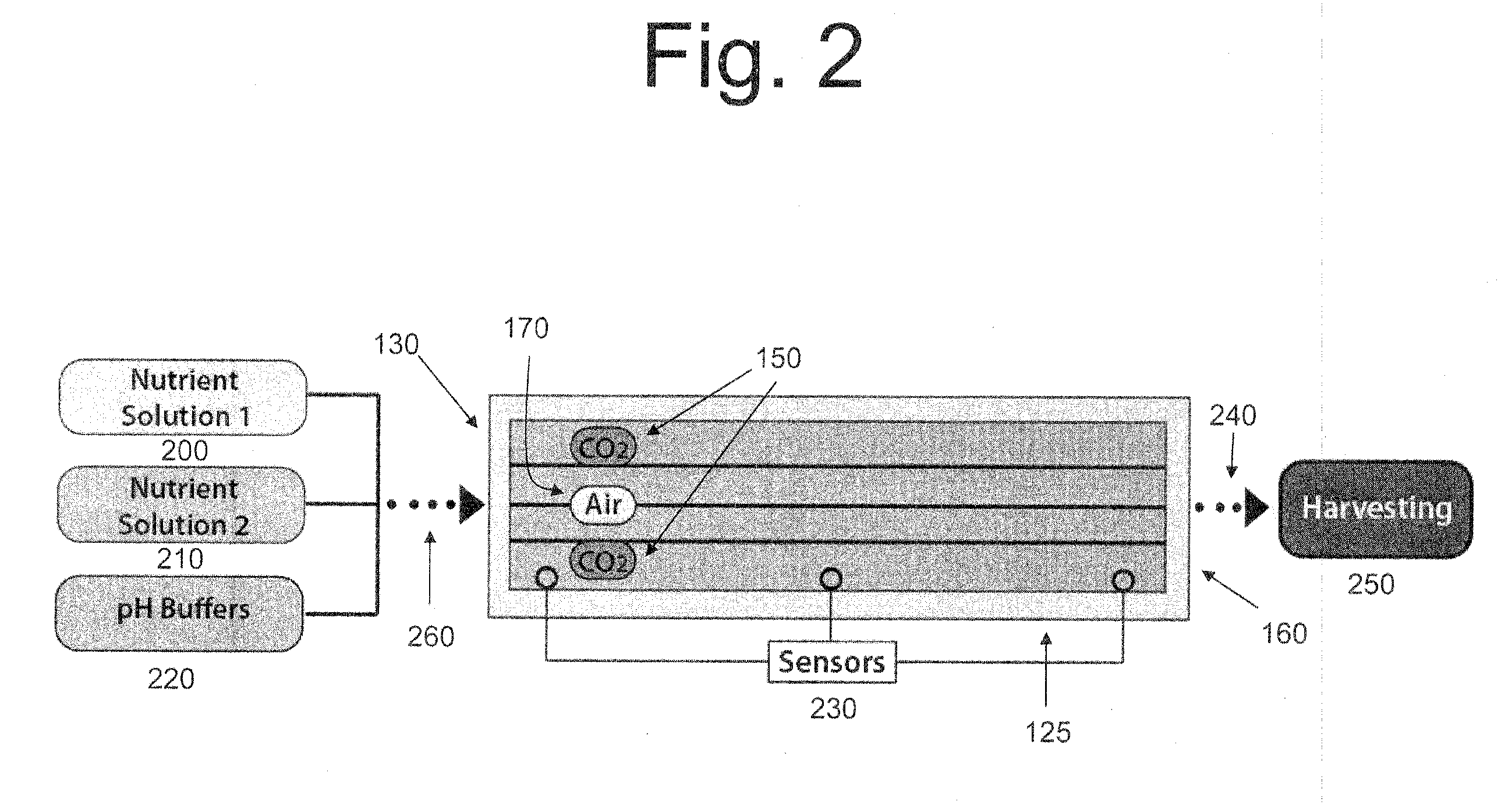
[0023]In one aspect, a photobioreactor is disclosed which comprises a cavity defined by: a substantially V-shaped base comprising: two base walls, said base walls meeting proximate to an axis defining an interior angle, each base wall comprising: a sloped portion and a substantially vertical portion, a proximal end and a distal end, and a length extending along said axis and a width extending perpendicular to said axis; the cavity being further defined by: a proximal side wall adjacent to said proximal end, and a distal side wall adjacent to said distal end; and the photobioreactor system further comprising: at least one gas delivery system disposed within said cavity and extending parallel to said axis, and at least one carbon dioxide delivery system disposed within said cavity and extending parallel to said axis.

[0024]In another aspect, a kit for assembling a photobioreactor is disclosed which comprises two base walls, a proximal side wall, a distal side wall and a first liner cap...


PUM


Abstract

Disclosed herein are photobioreactor systems for high productivity aquaculture or aquafarming for growing of algae or other organisms in an aquatic environment featuring aspects that favor improved growth rates by achieving control over the contents of the growth medium, including carbon source, nitrogen source, and essential trace elements necessary for growth. In one aspect, a photobioreactor is disclosed which comprises a cavity defined by: a substantially V-shaped base comprising: two base walls, said base walls meeting proximate to an axis defining an interior angle, each base wall comprising: a sloped portion and a substantially vertical portion, a proximal end and a distal end, and a length extending along said axis and a width extending perpendicular to said axis; the cavity being further defined by: a proximal side wall adjacent to said proximal end, and a distal side wall adjacent to said distal end; and the photobioreactor system further comprising: at least one gas delivery system disposed within said cavity and extending parallel to said axis, and at least one carbon dioxide delivery system disposed within said cavity and extending parallel to said axis. In other aspects, methods of use of these systems and kits for their assembly are disclosed.

Description

FIELD OF THE INVENTION[0001]Disclosed herein are photobioreactor systems for high productivity aquaculture or aquafarming for growing of algae or other organisms in an aquatic environment featuring aspects that favor improved growth rates by achieving efficient mixing rates, control over the contents of the growth medium, including carbon source, nitrogen source, and essential trace elements necessary for growth.BACKGROUND[0002]Algae have gained significant importance in recent years given their advantage in solving several critical global issues such as the production of renewable fuels and animal feedstock, reducing global climate change via carbon dioxide remediation, wastewater treatment, and sustainability. Algae farming is also used for the production of food, feed, nutraceuticals, chemicals, biofuels, pharmaceuticals, and other products that can be extracted from algae.[0003]Algae's superiority as a biofuel feedstock arises from a number of factors such as high per-acre produ...

Claims


Application Information

Patent Timeline
IPC IPC(8): A01G1/00
CPCA01G33/00C12M21/02C12M23/02C12M23/34C12M31/10C12M29/00C12M29/24C12M31/02C12M27/00Y02A40/80C12M3/00C12M1/00
Inventor LICAMELE, JASON D.WHITE, CARL L.
Owner HELIAE DEVMENT
Why Eureka
Try Eureka