Cooling Guide Catheter And Associated Method Of Use

a technology of cooling catheter and guide catheter, which is applied in the field of cooling catheter medical devices, can solve the problems of lingering heart damage, microvascular and endothelial injury, and myocyte damage through myocardial stunning, and achieve the effects of reducing flow-limiting wall drag, reducing near-wall viscosity, and improving cooling catheter blood flow performan

Inactive Publication Date: 2011-11-10
MERRILL THOMAS LAD
View PDF13 Cites 28 Cited by
  • Summary
  • Abstract
  • Description
  • Claims
  • Application Information

AI Technical Summary

Benefits of technology

[0035]Briefly stated, the present disclosure provides an cooling catheter in which blood in contact with cold surfaces is cooled and delivered to an injured organ to minimize reperfusion injury.
[0038]In a further embodiment, the cooling catheter is incorporated into a hybrid surface-infusion cooling device. Coolant infusion from coolant lumens within the catheter shaft into a central blood conveyance lumen enhances cooling catheter blood flow performance in two ways: 1) by reducing near-wall viscosity, reducing flow-limiting wall drag and 2) exchanging momentum with the blood flowing within the blood conveyance lumen.
[0039]In one embodiment a catheter apparatus provides a delivery system for standard intervention devices typically used during emergency angioplasty and to provide rapid localized cooling to organs at risk of ischemic and reperfusion injury. The catheter maintains the characteristics of existing guide catheters, leaving the current care path for emergency angioplasty unaltered, while also providing a means to cool organs at rates of 4 degree Celsius per 5 minutes or greater.
[0040]Besides the advantages of maintaining current guide catheter delivery features with cooling capabilities, embodiments of the present disclosure provide: (a) a catheter that is structurally designed to be steered, without kinking or torsional energy storage, to the organ at risk of ischemic and reperfusion injury; (b) a catheter that is shaped like a standard guide catheters to enable coaxial engagement with target vessels; (c) a catheter that is able to engage the target vessel easily and safely using radiopaque and atraumatic features; (d) a catheter that has sufficient internal lumen size and surface that allows low resistance insertion of a variety of interventional tools such as guidewires, dilation catheters with stents, diagnostic catheters, and thrombectomy catheters while continuously delivering cooled blood to an injured organ; (e) a catheter that cools blood to at least 28 degrees Celsius at flow rates of 30-100 ml / min; (f) a catheter that can provide the above mentioned cooling capability without external blood pumps; and (g) a catheter that can carefully control the organ-specific cooling process through using temperature, pressure, and flow sensors.

Problems solved by technology

Reperfusion injury results in myocyte damage through myocardial stunning, microvascular and endothelial injury, and irreversible cell damage or necrosis.
Despite hypothermia therapy's potential to attenuate myocardial necrosis, no cooling device has achieved approval for percutaneous coronary intervention because: 1) they complicate or impede the care path; and 2) they have not demonstrated significant clinical benefits.
Reducing lingering heart damage following a heart attack due to reperfusion injury continues to be a large unmet need.
While this approach is considered noninvasive, rapid temperature drop of organs at risk is not possible, rates of body temperature decrease are only about 3.2 degree Celsius per hour.
Again, these approaches do not allow for rapid organ cooling; whole-body cooling rates range from 2 to 5 degrees Celsius per hour.
These passively enhanced techniques also consume fluid kinetic energy, reducing blood flow and potentially re-creating ischemic conditions, making them less suited for low flow, small diameter applications as found in organ arteries.
In addition whole-body cooling has additional limitations and drawbacks related to its inherent unselective nature.
Research has shown that systemic or whole body cooling may lead to cardiovascular irregularities such as reduced cardiac output and ventricular fibrillation, an increased risk of infection, and blood chemistry alterations.
Few concepts have attempted local, organ-specific cooling.
Local cooling approaches have been limited by the technological challenges related to developing sufficiently small heat exchangers for small arterial vessels.
Organ tissue closest to the blockage, called the ischemic core, is most vulnerable to irreversible damage.
Often, the physical features of conventional catheter medical devices do not allow for integration with emergency angioplasty interventional tools, namely from a flexibility and size perspective.
Whole-body cooling, however, does not address organ-specific reperfusion injury resulting after an ischemic event, the clinical problem that this patent addresses As described earlier, there are several existing external and internal whole-body cooling devices that produce cooling rates ranging from 2-5 degrees Celsius per hour.
In addition to not providing a means for rapid organ-specific cooling, the '234 Evans et al. device has several disadvantages from a guide catheter perspective.
Second, inflation and deflation of the external balloons make device removal from the patient more difficult and will likely require a large insertion sheath than is typically needed.
Increased insertion sheath sizes lead to longer healing times and increased complications, the motivation in the commercial market for continued reduction in guide catheter sizes since the angioplasty procedure was introduced.
Third, the external balloons will naturally limit the maneuverability of the distal tip as the walls of the aorta are used to buttress or support proper guide catheter placement.
Fourth, the lubriciousness of the inner and outer surfaces is unclear.
The Ginsburg devices have several disadvantages against application to reduce tissue damage arising from reperfusion injury following emergency angioplasty procedures.
As a result, embodiments do not address torque control, kink resistance, and support characteristics through catheter shaft design.
Second, even if the flap was bent to meet the radius of curvature of the inner diameter of the circular device, flap deflection would be inhibited or perhaps prohibited completely because of the orthogonal curvature relative to the desired axis of rotation.
No existing catheters implement this valve design.
First, the double concentric design limits fluid pumping rates because the hydraulic diameters are inherently reduced due to the concentric nature of the design.
Impeding liquid flow reduces heat transfer coefficients and creates a longer residence time for the liquid to travel the path length.
This arrangement, based on established heat transfer references, inherently limits the maximum possible heat transfer possible substantially, typically 20% to 60% less than counter current flow arrangements depending upon the setup of the heat exchanger.
In addition, the double concentric design of the device of the '383 Ginsburg patent inherently limits the overall heat exchange process because the returning flow in the outer annulus is exchanging heat with inner annulus flow.
Third, blood flow entry into the inner most or central lumen via the depicted valves of the '383 Ginsburg references is inherently limited.
These factors hinder the ability of blood to flow at a fixed pressure difference, an undesirable condition for arterial blood flow to already ischemicly damaged organs.
Fourth, the arrangement and orientation of the valves in the Ginsburg devices, along the shaft perimeter of the patent prevent or at least substantially hinder coolant flow along the length of the catheter.
The designs do not apply heat exchanger best practices well established for decades such as maximizing hydraulic diameters to reduce coolant pressure drop and using counter current flow configurations that maximize the potential heat transfer.

Method used


Image

  • Cooling Guide Catheter And Associated Method Of Use
  • Cooling Guide Catheter And Associated Method Of Use
  • Cooling Guide Catheter And Associated Method Of Use

Examples


Embodiment Construction

[0078]The following detailed description illustrates the invention by way of example and not by way of limitation. The description enables one skilled in the art to make and use the present disclosure, and describes several embodiments, adaptations, variations, alternatives, and uses of the present disclosure, including what is presently believed to be the best mode of carrying out the present disclosure.

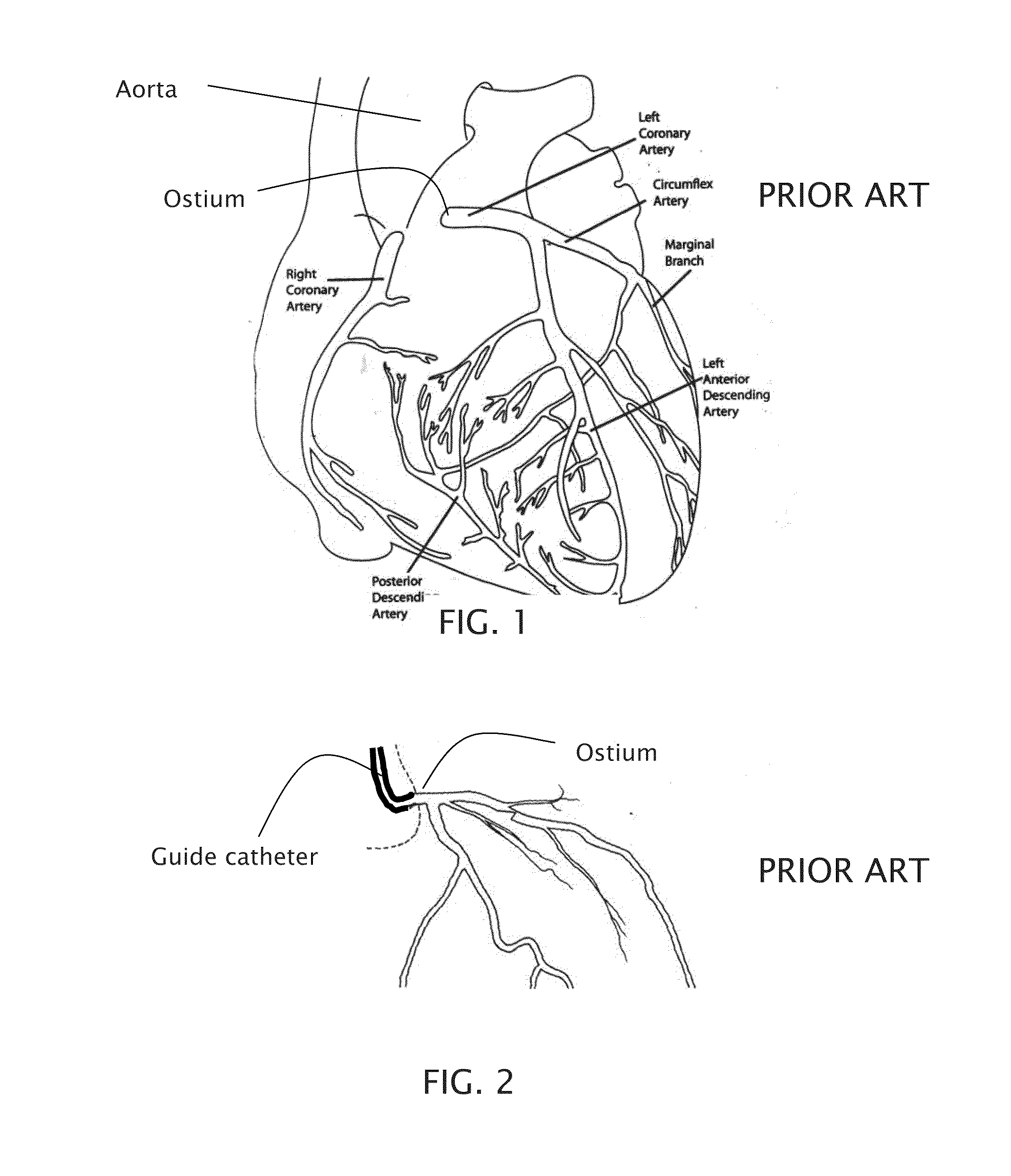
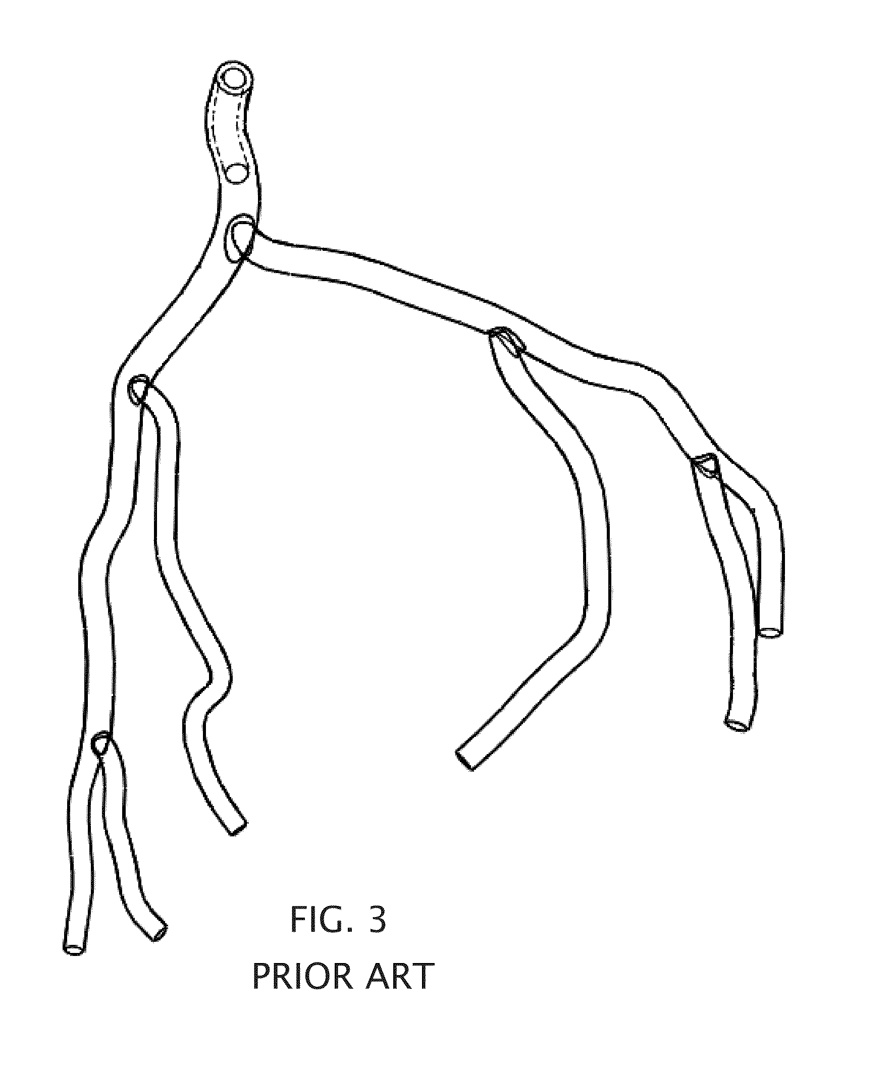
[0079]Turning to the figures, is can be seen that FIG. 1 through FIG. 3 shows the physiological landscape where embodiments of the present invention can be used. FIG. 1 shows a drawing of the major arteries of the heart. The coronary arteries (as seen in FIGS. 1-3) have proximal inner diameters ranging from 1.5 to 4.0 mm and length ranging from 2-4 cm. These arteries taper down in the direction of blood flow. FIGS. 2 and 3 show proximal and full engagement of a conventional guide catheter in the left main coronary artery, respectively. The large arteries carry out bulk transport of ...


PUM

PropertyMeasurementUnit
inner diameteraaaaaaaaaa
inner diametersaaaaaaaaaa

Abstract

A catheter apparatus configured to provide a delivery system for standard intervention devices typically used during emergency angioplasty and to provide rapid localized cooling to organs at risk of ischemic and reperfusion injury. The catheter apparatus including a catheter shaft having an inner core defining at least two coolant flow lumens adjacent to a blood conveyance lumen. Each coolant flow lumen in thermal contact with the blood conveyance lumen and thermally insulated from each other and the exterior surfaces of the catheter shaft.

Description

CROSS-REFERENCE TO RELATED APPLICATIONS[0001]The present application is a continuation-in-part of, and claims priority from, co-pending U.S. patent application Ser. No. 11 / 226,683 filed on Sep. 14, 2005, which is herein incorporated by reference. The '683 application in turn claims priority to U.S. Provisional Patent Application Ser. No. 60 / 610,333 filed on Sep. 16, 2004, and to U.S. Provisional Patent Application Ser. No. 60 / 650,297 filed on Jan. 26, 2005, both of which are herein incorporated by reference, and from which priority is claimed.STATEMENT REGARDING FEDERALLY SPONSORED RESEARCH[0002]The National Institute of Health provided support for the subject matter of this patent application under Grant #1 R43NS049933-01A1 (An Active Mixing Catheter For Selective Organ Cooling) and the United States government may have certain rights in this application.BACKGROUND OF THE INVENTION[0003]The present invention relates generally to a cooling catheter medical device such as may be used...

Claims


Application Information

Patent Timeline
Patent Type & Authority Applications(United States)
IPC IPC(8): A61F7/12B65H81/06
CPCA61F2007/126A61F7/12
Inventor MERRILL, THOMAS LAD
Owner MERRILL THOMAS LAD
Why Eureka
Try Eureka