Thermocouple device

a thermocouple and printed technology, applied in the manufacture/treatment of thermoelectric devices, instruments, heat measurement, etc., can solve the problems of difficult and sometimes impossible control of temperature measurement capability at a specific location during the procedure, generally not suitable for use on flexible/irregular surfaces, and the thermocouple is somewhat fragile, etc., to achieve more compact, less likely, and more streamlined

Active Publication Date: 2011-11-17
MICROPEN TECH CORP
View PDF23 Cites 50 Cited by
  • Summary
  • Abstract
  • Description
  • Claims
  • Application Information

AI Technical Summary

Benefits of technology

[0017]A further aspect of the present invention relates to a method of forming a thermocouple device. The method comprises applying a first metal containing ink composition to a flexible non-planar substrate, where the first metal containing ink composition forms a first printed thermocouple element and applying a second metal containing ink composition to the first metal containing ink composition applied to the flexible non-planar substrate where the second metal containing ink composition forms a second printed thermocouple element. The first and second metal containing ink compositions have a Seebeck coefficient sufficiently different from one another so that the first and second printed thermocouple elements together produce a thermocouple effect.
[0018]Thermocouples have...

Problems solved by technology

Accurate measurements of tissue or body fluids temperature are critically important during many medical procedures, but introduction of temperature measurement capability at a specific, controllable location during the procedure is often difficult and sometimes impossible.
As useful and versatile as modern thermocouples might be, they suffer from certain disadvantages, among which are that they are generally not suitable for use on flexible/irregular surfaces.
Thermocouples are often made of thin wire pairs so that the device responds more quickly to temperature changes, but such a construction can make the thermocouple somewhat fragile.
Several inventions have been aimed at demonstrating and solving the problems inherent in placing a temperature-measuring device directly on or in a medical device, but they have drawbacks and technical limitations.
However, the objects must be held against a noncompliant backing during printing, such that silk screening is limited to two-dimensional or planar surfaces.
Most medical devices of interest are polymeric, flexible, and three dimensional, rendering the silk screening approach problematic and often unusable.
Mounting the thermistor rather than writing it directly on the tube surface leads to unwanted protrusion on the surface of the device which may prove damaging or uncomfortable upon introduction of the device to measure temperature during medical procedures.
Further, there is an increased risk of the temperature sensor becoming loose and ge...

Method used


Image

  • Thermocouple device
  • Thermocouple device
  • Thermocouple device

Examples


example 1

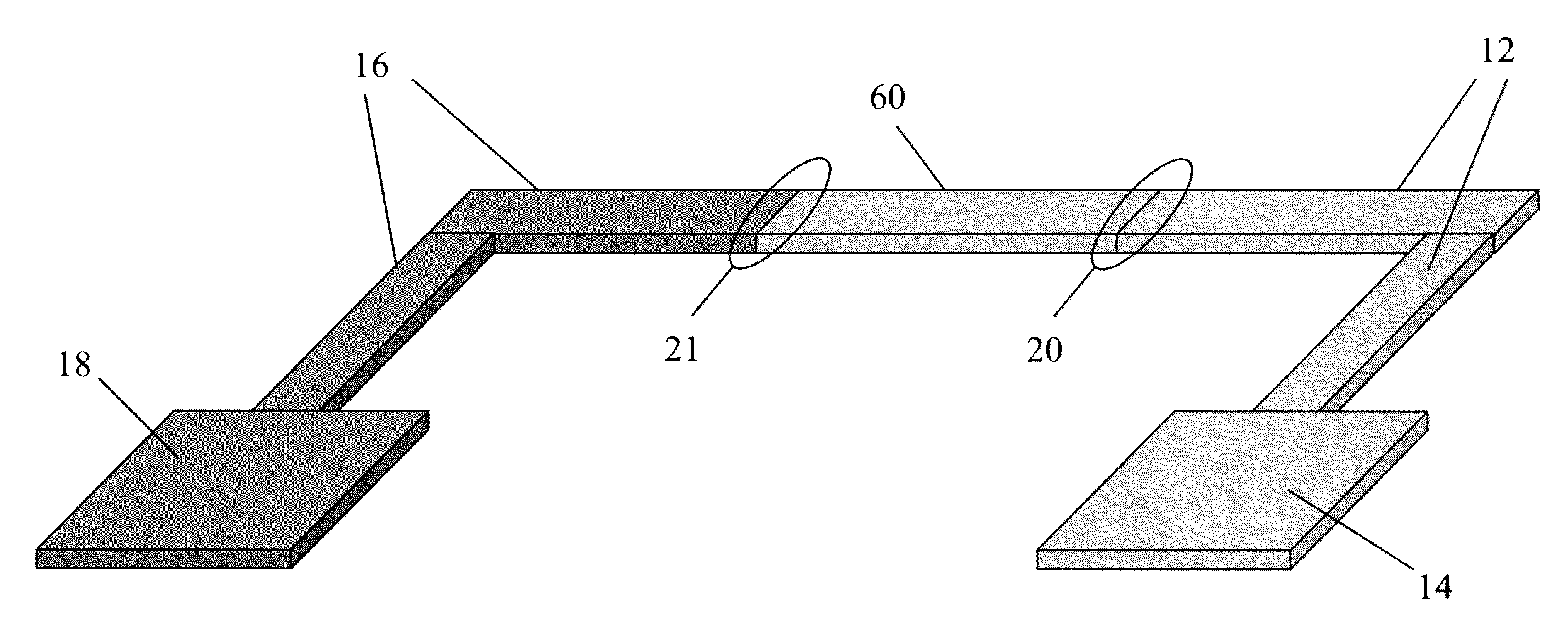
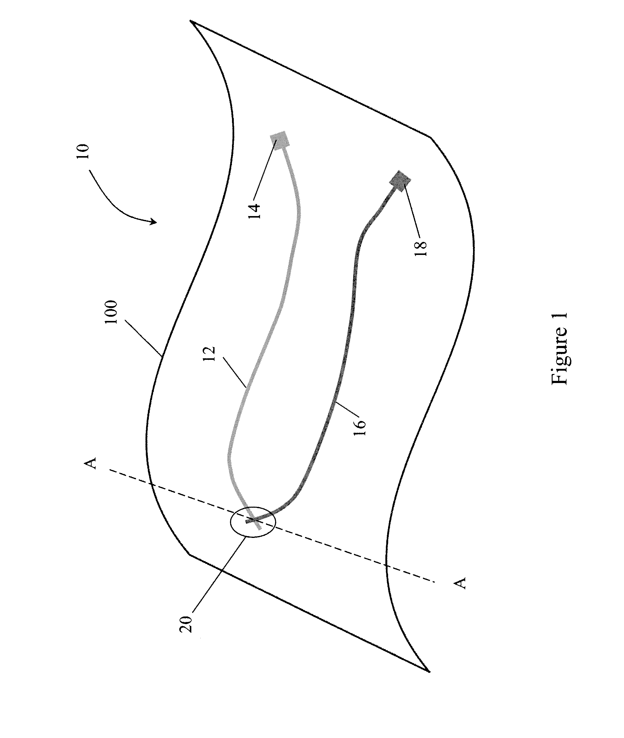
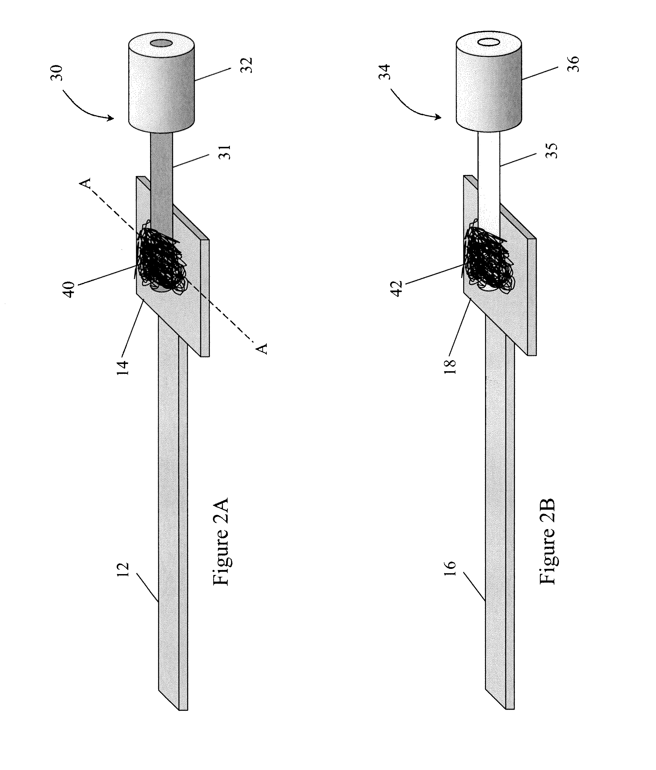
Method of Making the Thermocouple

[0089]Silver ink was prepared by dissolving poly(vinyl chloride) (high molecular weight, Sigma ALDRICH® at a level of 13% by weight in a mixture of tetrahydrofuran, n-methyl pyrrolidone and a-terpineol in a ratio of 55:36:9 by weight. Silver flake (10 μm, >99.9%, SIGMA-ALDRTCH® was added to yield a ratio of silver:poly(vinyl chloride) of 85:15. The total solids were 50% by weight. In order to enable a thorough mixing, the materials were combined using a planetary high shear mixer (KURABO MAZERUSTAR KK-50S)

[0090]Nickel ink was prepared by dissolving poly(vinyl chloride) (high molecular weight, Sigma-ALDRICH® at a level of 13% by weight in a mixture of tetrahydrofuran, n-methyl pyrrolidone and a-terpineol in a ratio of 67.5:26:6.5 by weight. Nickel powder (3 μm, 99.7%, SIGMA-ALDRTCH® was added to yield a ratio of nickel:poly(vinyl chloride) of 85:15. The total solids were 44% by weight.

[0091]The inks were loaded into syringes and extruded through a Mic...

example 2

Testing of Cyclohexane as a Solvent to Prepare Thermocouple

[0096]Thermocouples were prepared in a manner identical to that described in Example 1, except the solvent used for the inks was cyclohexanone. Also, nickel flake (−325 mesh, 0.37 microns thick, 99.8%, Alfa Aesar®) was used instead of nickel powder, and the final percentage of solids of the nickel inks was adjusted to 46% by weight.

[0097]Junctions and traces were printed onto the surface of an endotracheal tube using Micropen® direct writing device as described in Example 1—i.e. cured, covered with a polymeric encapsulant, and leads attached as described previously.

[0098]The printed thermocouple junction on the tube was tested as described in Example 1, except in this case the maximum temperature was raised to 130° C., yielding a response of 20 μV / C for heating and cooling.

[0099]The thermocouple junction on the cuff was evaluated similarly, except the maximum temperature reached was 140° C. Also, after the heating cycle was ...

example 3

Use of Commercially Available Metallic Inks to Make Thermocouples

[0100]Thermocouples were prepared identically to Example 1, except commercially available metallic inks were use. The silver ink used was 101-59 (Creative Materials, Inc. (Tyngsboro, Mass.)) and the nickel inks used was 116-25 (Creative Materials, Inc. (Tyngsboro, Mass.)). The nickel ink was bonded to the nickel wire using the nickel ink as an adhesive; and the silver wire was bonded using a silver epoxy (Epo-Tek® H20E; Epoxy Technology, Inc (Billerica, Mass.)).

[0101]A thermocouple junction positioned on the cuff was evaluated on heating and cooling from 25° C. to 145° C. and back, and had a sensitivity of 20 μV / ° C.


PUM


Abstract

In one aspect, the present invention relates to a thermocouple device comprising a flexible non-planar substrate, a first printed thermocouple element comprising a first metal containing ink composition applied to the flexible non-planar substrate, and a second printed thermocouple element in electrical contact with the first printed thermocouple element making a thermocouple junction. The second printed thermocouple element comprises a second metal containing ink composition with a Seebeck coefficient sufficiently different from the first metal containing ink composition for the first and second printed thermocouple elements to together produce a thermocouple effect. The present application further relates to medical devices comprising the thermocouple and methods of making such devices.

Description

[0001]This application claims the benefit of U.S. Provisional Patent Application Ser. No. 61 / 315,534, filed Mar. 19, 2010, which is hereby incorporated by reference in its entirety.FIELD OF THE INVENTION[0002]The present invention is related to a printed thermocouple device and its uses.BACKGROUND OF THE INVENTION[0003]Common options for measuring temperature include the Resistance Temperature Detector (RTD), which has a metallic element possessing a positive temperature coefficient of resistance (decreasing resistance with increasing temperature), or a thermistor, which has a metal oxide element exhibiting a negative temperature coefficient (increasing resistance with increasing temperature). Unlike an RTD, thermocouples can achieve high accuracy without any restrictions on target immersion depth relative to the sensor diameter or length. Unlike a thermistor, thermocouples produce signals without any pronounced nonlinearity with temperature, thus allowing use over a greater tempera...

Claims


Application Information

Patent Timeline
IPC IPC(8): H01L35/02H01L35/34B41F33/00H01L35/32
CPCA61B18/14A61B2018/00821H01L35/32G01K7/028G01K13/002A61B2019/5466A61B2090/3966G01K13/20H10N10/17
Inventor GRANDE, WILLIAM J.SHAW-KLEIN, LORI J.MIN, LI
Owner MICROPEN TECH CORP
Why Eureka
Try Eureka