Self-collimator planar spectroscopy shaping device for chirped-pulse-amplification

a spectroscopy and shaping device technology, applied in the direction of spectrometry/spectrophotometry/monochromators, instruments, optical radiation measurement, etc., can solve the problems of reducing the amplification efficiency of chirped pulses, affecting the enhancement of laser output, and cpa distortion, so as to achieve compact construction and reduce the need for laboratory space , the effect of easy fabrication

Inactive Publication Date: 2011-11-17
LI MING +4
View PDF5 Cites 5 Cited by
  • Summary
  • Abstract
  • Description
  • Claims
  • Application Information

AI Technical Summary

Benefits of technology

[0007]The present invention seeks to provide an improved pulse shaping method to overcome the defects in the traditional shaping methods mentioned above. The new self-collimator planar spectroscopy shaping device for chirped pulse amplification is proposed based on an improved Czerny-Turner Spectrum Instrument (CTSI) system, which involves two symmetrical CTSI systems, called a spectrum decomposing system and a spectrum synthesizing system respectively, and it involves a spectrum shaping system. The process is as following: firstly, the chirped pulse is spread totally the frequency components of chirped pulse into a spatial place by the spectrum decomposing system. Then, its spectrum is modulated and shaped by the modulation system in the focus plane. And then, the spatial light is integrated un-shiftily by the spectrum synthesizing system back to a designed shape chirped pulse, which accomplishes the spectrum modulating and shaping function. The present invention solves the problem that the traditional shaping method in the world is not practical for a over terawatt (1012) system or is unusable for a Nd:glass system narrow bandwidth system. And the present invention can be not only utilized for a general laser spectrum shaping and spectrum modulating, but also especially utilized for a high energy and ultra-high peak-power laser systems with a few nanometers bandwidth and a large caliber in the CPA system. This device has the features of compacted in the structure, less space requiring, and running stability, because of its small size of concave reflector, and its self-collimation and its symmetrical distribution. The functional reflector can be manufactured in a large diameter and can be designed on a high damage threshold, so the present invention device can be inserted anywhere in the amplifier chain in the CPA system for enlarging energy and reducing the pedestal of the output. The spectrum modulation ratio can be varied over 60% under the condition that the phase of the reflecting light remains nearly constant. The chromatic resolving capability of about 0.1 nm and the phase aberration in the range of the tens of nanometer of up to 12 mrad, which can meet the requirement of the kilo joule peta-watt-class reconstruction project.

Problems solved by technology

In the field of the high-power ultra-short laser pulse amplification, the enhancement of the output of a laser system is hampered by a series of factors such as the gain narrowing effect and the gain saturation effect in the solid state laser amplification medium.
The gain saturation effect is another main factor leading to the distortion of CPA.
Hence the output of amplified pulse becomes asymmetric in the pulse waveform, which leads to the lose of amplification efficiency of chirped pulse, which leads to the red shift effect in the spectrum of the laser pulse, and which leads to the distortion of CPA.
The above literatures also illustrate some defects in the traditional shaping methods, just as following: 1. Using the thin etalon in regenerative amplification to tune the spectrum of the laser pulse, but it is complexity of the device regulation, in addition, a optical parametric chirped pulse amplifier (OPCPA) has substituted the regenerative amplifier in the front-end of kilojoules peta-watt-class laser system, so this method does not apply.
Using the center wavelength blue shift injection, that is, making the centre of the pulse wavelength blue shift relative to the centre wavelength of the medium spontaneous emission, making the long wavelength parts of the pulse with a large duration, and making the spectrum modulation directly, but it is not practical to a over terawatt (1012) system.
Using the long-wavelength injection method that utilizes narrowing effect to compensate saturation effect, but this will make the system unstable.
Furthermore, the above literatures also illustrate some defects in the transmission shaping methods, just as following: 1. Using the interference filter for selective transmission, but it exists difficulty both in the principle of design and in the fabrication techniques, such as the principle of design can not avoid the Fabry-Perot (FP) side effect.
When the modulation bandwidth is less than tens nanometers, the fabrication techniques can not control the bandwidth and the depth in the centre wavelength of the transmittance curve according to the limit of the coating techniques.
Using the combination lens of birefringent crystal for the selective transmission, here the interference between the ordinary light and the extraordinary light conducts the selective transmission, but it exists difficulty both in the principle of design and in the fabrication techniques.
For example, the transmitted element can not avoid the side effect such as FP effect and the distortion of phase etc.
For instance, if the spectrum bandwidth of the ultra-short pulse is 13 nm, the thickness of the birefringent crystal must be 25 mm; however, the size of birefringent crystal can not be produced that large.

Method used


Image

  • Self-collimator planar spectroscopy shaping device for chirped-pulse-amplification
  • Self-collimator planar spectroscopy shaping device for chirped-pulse-amplification
  • Self-collimator planar spectroscopy shaping device for chirped-pulse-amplification

Examples


example 1

OF THE DEVICE

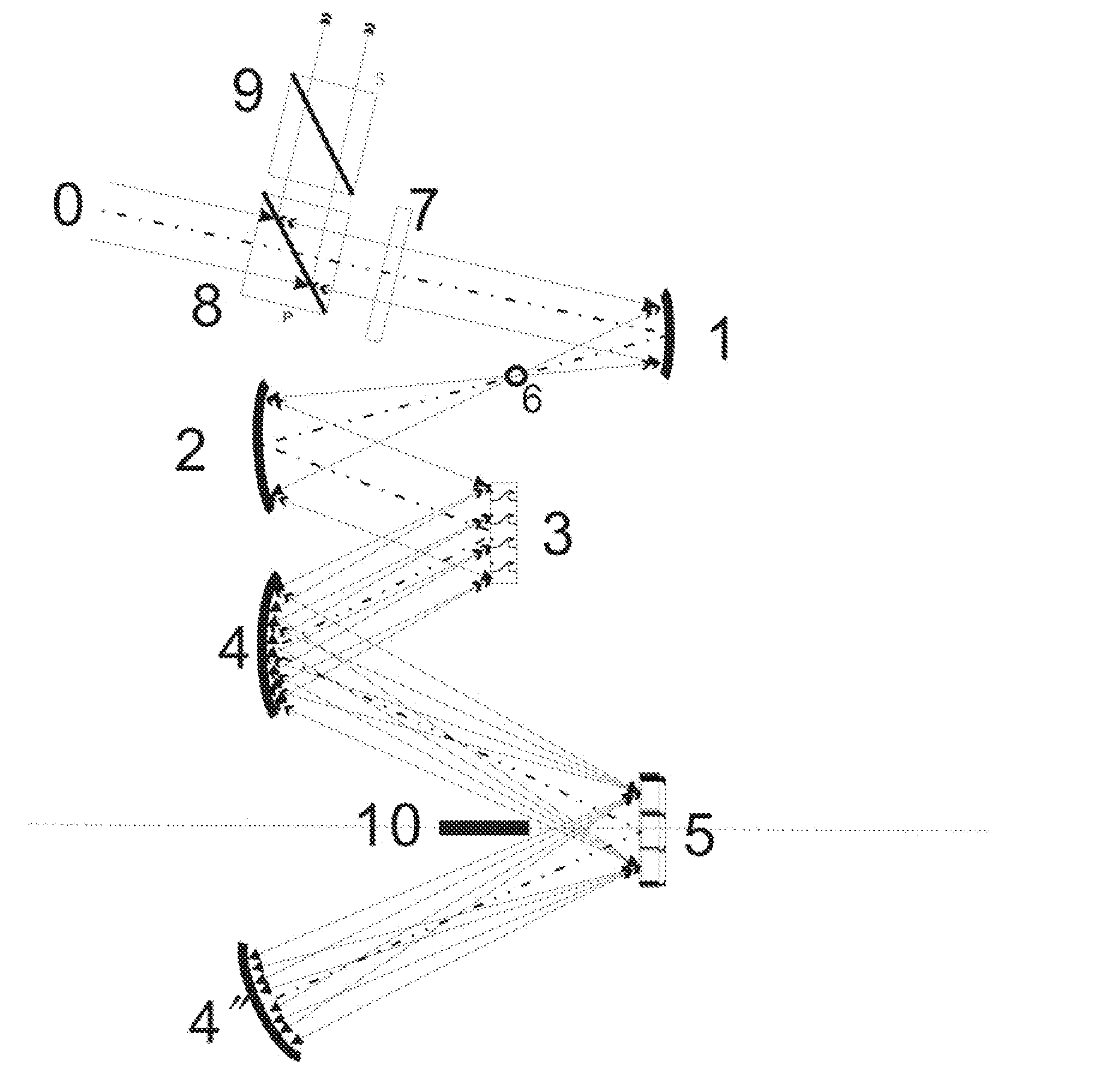
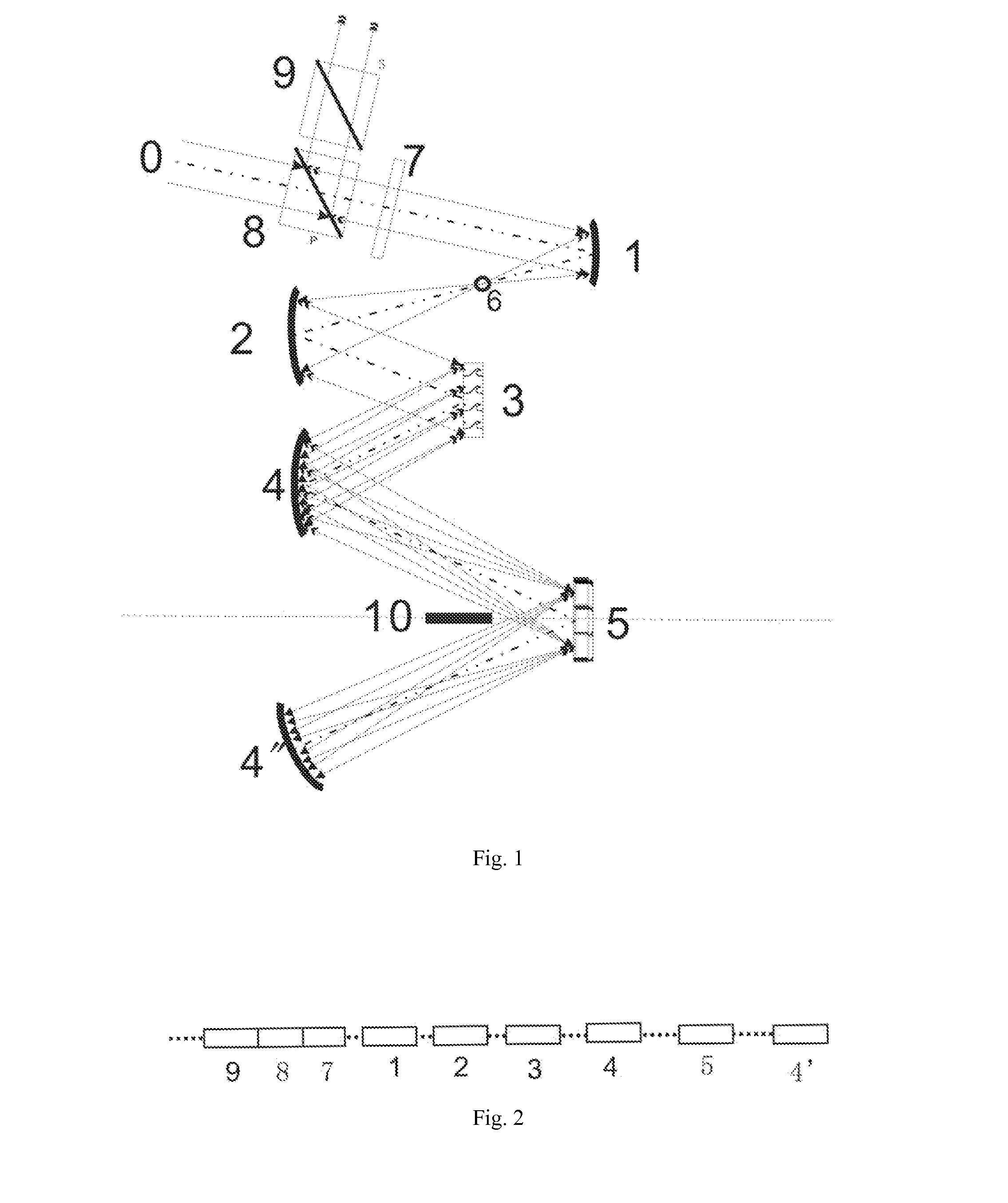
[0081]In this example 1, there are those: the 3 is the reflective planar blazed grating, which can endure the high power laser damage and can be fabricated in a large caliber. The 5 is a multilayer dielectric thin film with micro-structures in it. The 1, the 2, the 4, and the 4″ are concave reflectors, which are made in strictly eliminated the chromatic aberration, the spherical aberration, and the comatic aberration, to ensure the maximal deviation between the spectrum image plane and the planar reflector for spectrum shaping function design less than the tolerance of the half focal depth deduced from the Rayleigh's Criterion. The 6 is an aperture diaphragm, and the 10 is a slit diaphragm that is composed of a light barrier and its image in the 5. The 6 is the incident aperture, and also is the output aperture; the 10 is the middle aperture.

[0082]FIG. 1 schematically illustrates the structure of a self-collimator planar spectroscopy shaping device, which the above elem...

example 2

OF THE DEVICE

[0087]In this example 2, there are those: the 3 is the reflective planar blazed grating, which can endure the high power laser damage and can be fabricated in a large caliber, and which is working under the primary maximum of interference of the minus first (−1) level. The 5 is a multilayer dielectric thin film as a planar reflector for spectrum shaping with micro-structures in it. The 1, the 2, the 4, and the 4″ are concave reflectors, which are made with strictly eliminating the chromatic aberration, the spherical aberration, and the comatic aberration, to ensure the maximal deviation between the spectrum image plane and the planar reflector for spectrum shaping function design less than the tolerance of the half focal depth deduced from the Rayleigh's Criterion; The 6 is an aperture diaphragm, and the 10 is a slit diaphragm that is composed of a light barrier and its image in the 5; the 6 is the incident aperture, and also is the output aperture; the 10 is the middle...

example 3

OF THE DEVICE

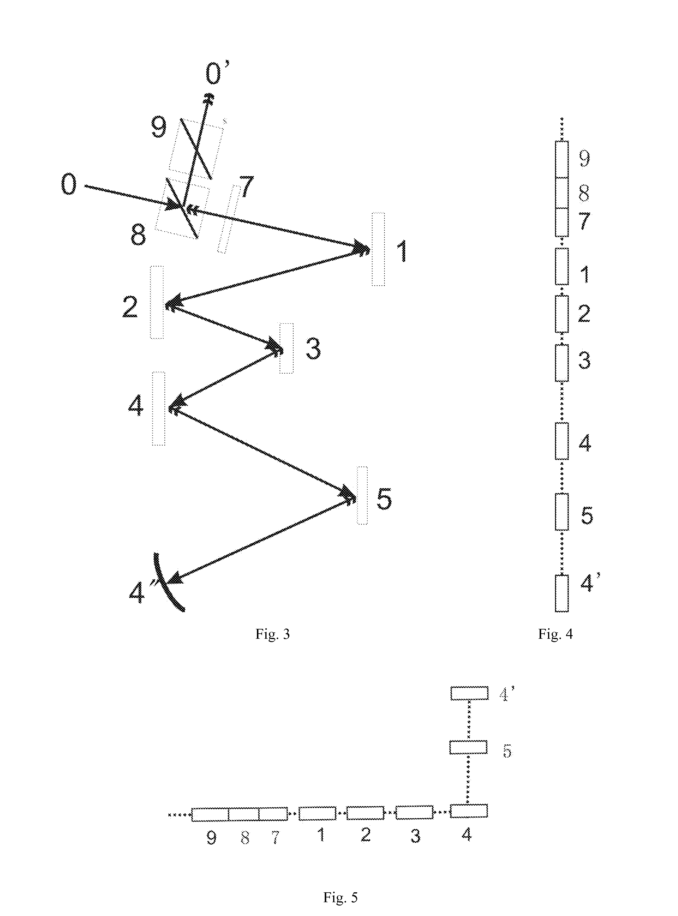
[0093]In this example 3, there are those: the 3 is the reflective planar blazed grating, which can endure the high power laser damage and can be fabricated in a large caliber; the 5 is a multilayer dielectric thin film as a planar reflector for spectrum shaping with micro-structures in it; The 1, the 2, the 4, and the 4″ are concave reflectors, which are made in strictly eliminated the chromatic aberration, the spherical aberration, and the comatic aberration, to ensure the maximal deviation between the spectrum image plane and the planar reflector for spectrum shaping function design less than the tolerance of the half focal depth deduced from the Rayleigh's Criterion; The 6 is an aperture diaphragm, and the 10 is a slit diaphragm that is composed of a light barrier and its image in the 5; the 6 is the incident aperture, and also is the output aperture; the 10 is the middle aperture.

[0094]FIG. 1 schematically illustrates the structure of a self-collimation CTSI spectru...


PUM


Abstract

A self-collimator planar spectroscopy shaping device for chirped pulse amplification (CPA): uses a spectrum decomposing system with CTSI construction, a spectrum synthesizing system with CTSI structure that is symmetrical to the decomposing structure, and a spectrum shaping system including an aperture and a planar reflector for spectrum shaping function design. The device accomplishes the following functions: firstly decomposing the spectrum of a chirped temporal pulse laser to a spectral domain; then shaping the spectrum in the spectral domain; finally synthesizing un-shiftily this shaped spectrum in the spectral domain into a temporal chirped pulse with a designed shape. The device has features of small size of concave reflector, easy fabrication, compact construction, little laboratory space needed, and cheap in cost, which it can be different types of configuration for different circumstance application, which it can be not only utilized in a general laser spectrum shaping and spectrum modulation, but also can be utilized for a high energy and ultra-high peak-power laser system in chirped pulse amplification with a large caliber and with a chirped pulse bandwidth of a few nanometers.

Description

PRIORITY CLAIM[0001]The application titled as a self-collimator planar spectroscopy shaping device for chirped-pulse-amplification is the international application, PCT / IB2009 / 050915, filed on 3 May 2009, for entry into the national stage in the United States, where it claims the benefit of the international filing date of the international application designating the United States of America.TECHNICAL FIELD OF THE INVENTION[0002]The present invention relates generally to a pulse shaping device for laser amplification in the power. The invention related in particular to manipulating the spectral and temporal characteristics of laser pulses, which the self-collimator planar spectroscopy shaping device for chirped pulse amplification is for a large caliber and high power chirped pulse amplification (CPA) in huge energy, which belongs to the filed of application technology of engineering optics.DISCUSSION OF BACKGROUND ART[0003]In the field of the high-power ultra-short laser pulse amp...

Claims


Application Information

Patent Timeline
Patent Type & Authority Applications(United States)
IPC IPC(8): H01S3/063
CPCG01J3/18G01J2003/1213G01J2003/1282G02B27/0927G02B19/0023G02B27/0983G02B27/30H01S3/005G02B19/0052G02B27/0944G02B17/0668
Inventor LI, MINGDAI, YAPINGWANG, TAOZHANG, BINFAN, ZHENGXIU
Owner LI MING
Why Eureka
Try Eureka