Low co2 emissions systems

a co2 emission and low energy technology, applied in the direction of waste based fuel, machines/engines, combustible gas catalytic treatment, etc., can solve the problems of excessive harmful emissions, inability to store electrical power, and inefficient modern power plants to efficiently enable the throttling back of electrical power production, etc., to enhance algae growth

Inactive Publication Date: 2011-12-01
JURANITCH JAMES CHARLES
View PDF3 Cites 20 Cited by
  • Summary
  • Abstract
  • Description
  • Claims
  • Application Information

AI Technical Summary

Problems solved by technology

One of the significant disadvantages of conventional power plants is that when they are brought off-line, and then restarted, they are unacceptably inefficient and produce exceeding amounts of harmful emissions.
Modern power plants do not efficiently enable the throttling back of production of electrical power, and therefore they are operated continuously near the designed load limit.
Since electrical power cannot be stored, power plants are frequently shut down and restarted in response to the varying demand for electrical power by consumers on a day-to-day basis, and as a result of differences in demand between day and night conditions.
This known approach disadvantageously strains limited resources.
In addition to environmental effects, the known processes have resulted in political unrest, such as in China where the population battled over the rationing of fertilizer containing ammonia.
The political unrest resulted from the fact that the fossil fuels needed to produce the ammonia were preferentially redirected to other fuel starved areas.
It is believed that political problems will worsen in the future.
None of the operations in these countries use large scale renewable resources.
Electrolysis is generally not economically feasible for producers who are not blessed with hydroelectric power.
If the plasma melters are operated in a pyrolysis mode of operation, they will generate large amounts of hydrogen and carbon monoxide.

Method used


Image

  • Low co2 emissions systems
  • Low co2 emissions systems
  • Low co2 emissions systems

Examples


Embodiment Construction

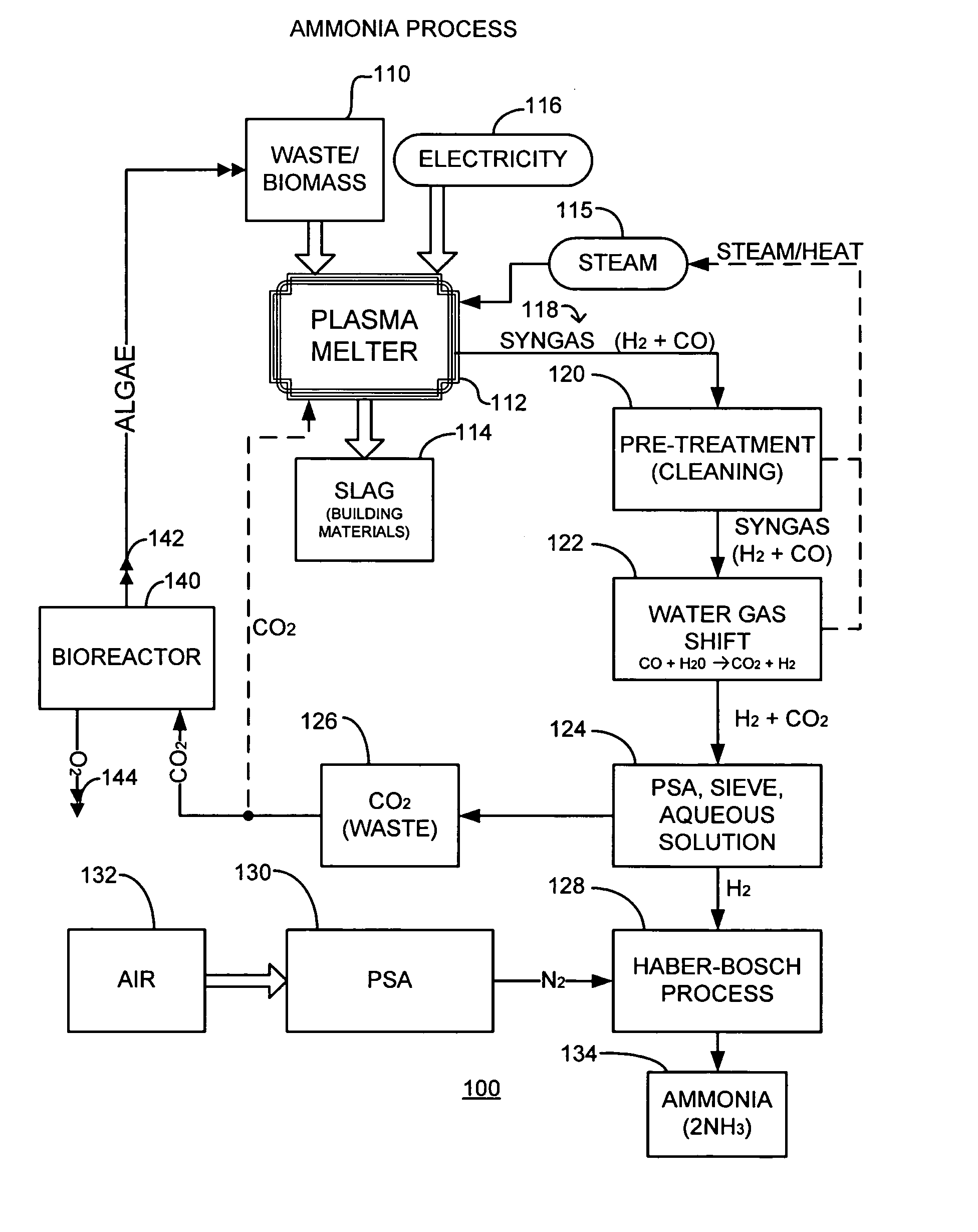
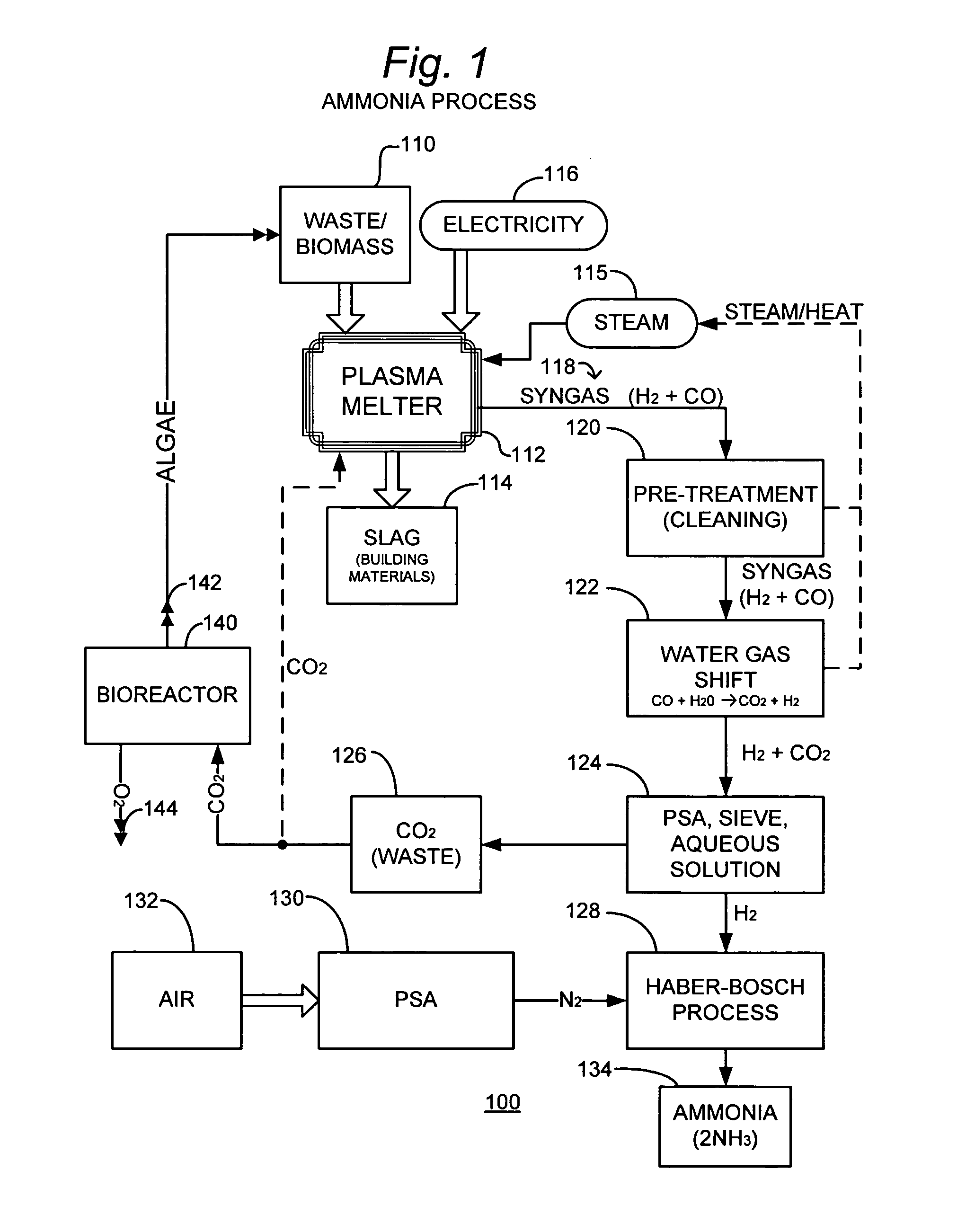
[0076]FIG. 1 is a simplified schematic representation of an embodiment of the invention wherein ammonia product is produced along with algae for use as a fuel. As shown in this figure, an ammonia producing system 100 receives municipal waste, or specifically grown biomass 110 that is deposited into a plasma melter 112. In the practice of some embodiments of the invention, the process is operated in a pyrolysis mode (i.e., lacking oxygen). Steam 115 is delivered to plasma melter 112 to facilitate production of hydrogen and plasma. Also, electrical power 116 is delivered to plasma melter 112. A hydrogen rich syngas 118 is produced at an output (not specifically designated) of plasma melter 112, as is a slag 114 that is subsequently removed.

[0077]In some applications of the invention, slag 114 is sold as building materials, and may take the form of mineral wool, reclaimed metals, and silicates, such as building materials. In some embodiments of the invention, the BTU content, plasma pr...


PUM

PropertyMeasurementUnit
molar ratioaaaaaaaaaa
electrical energyaaaaaaaaaa
pressureaaaaaaaaaa

Abstract

Systems and methods of generating power or producing gaseous products generate CO2 as a waste product or as a greenhouse gas. Rather than being discharged into the atmosphere, the CO2 is employed in a bioreactor to enhance the growth of algae. The algae then becomes a commercial product, or it can be consumed as fuel in the generation of power or the production of a gaseous product.

Description

RELATIONSHIP TO OTHER APPLICATIONS[0001]This application claims the benefit of the filing date of U.S. Provisional Patent Application Ser. No. 61 / 270,035, filed Jul. 3, 2009, Confirmation No. 9380 (Foreign Filing License Granted); and is a continuation-in-part of copending International Patent Application Ser. No. PCT / US2009 / 003934, filed Jul. 1, 2009, which claims the benefit of the filing date of U.S. Provisional Patent Application Ser. No. 61 / 133,596, filed Jul. 1, 2008; and is a continuation-in-part, and claims the benefit of the filing dates of, U.S. Provisional Patent Application Ser. Nos. 61 / 199,837, filed Nov. 19, 2008; 61 / 199,761 filed Nov. 19, 2008; 61 / 201,464, filed Dec. 10, 2008; 61 / 199,760, filed Nov. 19, 2008; 61 / 199,828 filed Nov. 19, 2008, and 61 / 208,483, filed Feb. 24, 2009; the disclosures of all of which are incorporated herein by reference.BACKGROUND OF THE INVENTION[0002]1. Field of the Invention[0003]This invention relates generally to systems for generating po...

Claims


Application Information

Patent Timeline
Patent Type & Authority Applications(United States)
IPC IPC(8): H02K7/18C07C27/06A01G1/00C01C1/04
CPCC01B3/56C10J2300/1681C10J2300/1815Y02E50/32C10K3/04C10J2300/1668C10J2300/1238C10J2300/1612C10J2300/1659C10J2300/1662C10J2300/0946Y02E50/30
Inventor JURANITCH, JAMES CHARLES
Owner JURANITCH JAMES CHARLES
Why Eureka
Try Eureka