System for treating a substance with wave energy from an electrical arc and a second source

a wave energy and wave energy technology, applied in the field of treating substances, can solve the problems of inefficiency of lamp, high radiation consumption of uv radiation system, and inability to maximize the use of electricity, and achieve the effects of reducing maintenance costs, reducing energy consumption, and reducing the number of uv radiation sources

Inactive Publication Date: 2011-12-15
FORET PLASMA LABS
View PDF0 Cites 56 Cited by
  • Summary
  • Abstract
  • Description
  • Claims
  • Application Information

AI Technical Summary

Benefits of technology

[0013]The present invention provides a system, method and apparatus for treating substances with wave energy from an electrical arc that: (1) is compact and portable, yet does not use mercury; (2) is energy efficient, rugged, low maintenance and compact; (3) can also remove fine sediment or reduce turbidity in water; (4) can also phase separate material of various densities from that of water, such as oil and grease, wood, leaves, and plastic bottles from water; and / or (5) can reduce organic matter in water. The substance can be drinking water, wastewater, beverages, juices, milk, emulsions, ballast water, bilge water, cooling tower water, process water, mill water, raw sewage, crude oil, hydrocarbon streams, black liquor or any pumpable substance. The present invention can operate in remote areas of the world that can deliver various forms of wave energy to the water and contaminants, and not simply UV radiation, that would aid in decomposing organics and producing a potable water source, which is needed immediately throughout the world. In addition, the present invention can be operated without line power by using a wind turbine or photovoltaic cells, which allows for remote treatment of water and wastewater without the need of a generator or line power.
[0014]The present invention generates a whirlpool or cyclonic flow and one or more wave energies in the “eye”“plasma core” or “hollow gas core” of the whirlpool. The present invention treats the substances or fluids by first irradiating the fluid with a plasma arc centrally located within the gas core of the whirling fluid, then second forming a thin film with the fluid and irradiating the thin film fluid and third reflecting the wave energy in order to increase the dose of wave energy absorbed by the fluid or matter within the fluid. The present invention can also provide an advanced oxidation / reduction process (AORP) for treating fluids utilizing a semi-conductor catalyst. Likewise, the present invention includes a means for introducing charged nano metals and minerals as well as carbon for treating water. Additionally, the present invention includes a phase separation mechanism.
[0015]The present invention, which will be described in detail below, provides superior wave energy delivery to the substance to be treated, a superior method for stripping and destroying volatiles in-situ and a method for subjecting fluids, contaminants and pathogens to several forms of wave energy simultaneously. In addition, the present invention provides a mechanism for treating substances with several forms of wave energy, such as ultraviolet radiation, vacuum ultraviolet radiation, infrared radiation, visible light radiation, microwave radiation, infrared radiation, sonic energy, ultrasonic energy, electrolysis or a combination thereof. Additionally, the present invention provides a mechanism for generating an oxidant or free radicals in-situ. Furthermore, the present invention utilizes a unique approach for disinfecting and filtering water within the same system. Hence, by the present invention's novel wave energy method for treating substances by eliminating the lamp, and using a carbon arc in combination with a whirling fluid, a system can be designed to treat very low flow rates using a wind turbine or photovoltaic cells to recharge DC batteries, while scaling up to treat volumes of water currently unheard of by using very large DC power supplies and graphite rods, commonly found within the foundry industry—carbon arc furnaces.

Problems solved by technology

This is primarily due to emerging pathogenic microorganisms that are resistant to many oxidants such as chlorine, as well as the problems associated with the byproducts formed by reacting chlorine with organics found in drinking water sources.
One of the main problems with existing UV radiation systems that incorporate mercury arc lamps is that they fail to maximize the use of electricity.
More particularly, by utilizing only the energy in the form of UV radiation converted from the electricity used in the overall electrical circuit—the lamp—is inefficient and requires higher doses of UV radiation than are necessary if more of the electrical energy in the electrical circuit could be utilized for pathogen inactivation or treatment of pollutants.
In addition, these lamps contain mercury, which is a pollutant that can be transferred via the food chain.
In addition, any UV radiation system incorporating a “bulb” is prone to burn out.
In addition, over time the quartz envelope that houses the lamp becomes dirty.
Consequently, the effectiveness of the UV radiation system to inactivate cryptosporidium is reduced over time as the lamp ages and the quartz sleeve or envelope becomes dirty.
In addition, low doses of UV light cannot be applied to meet sterilization or pasteurization guidelines as set forth by the US FDA, USDA and UPH.

Method used


Image

  • System for treating a substance with wave energy from an electrical arc and a second source
  • System for treating a substance with wave energy from an electrical arc and a second source
  • System for treating a substance with wave energy from an electrical arc and a second source

Examples


second embodiment

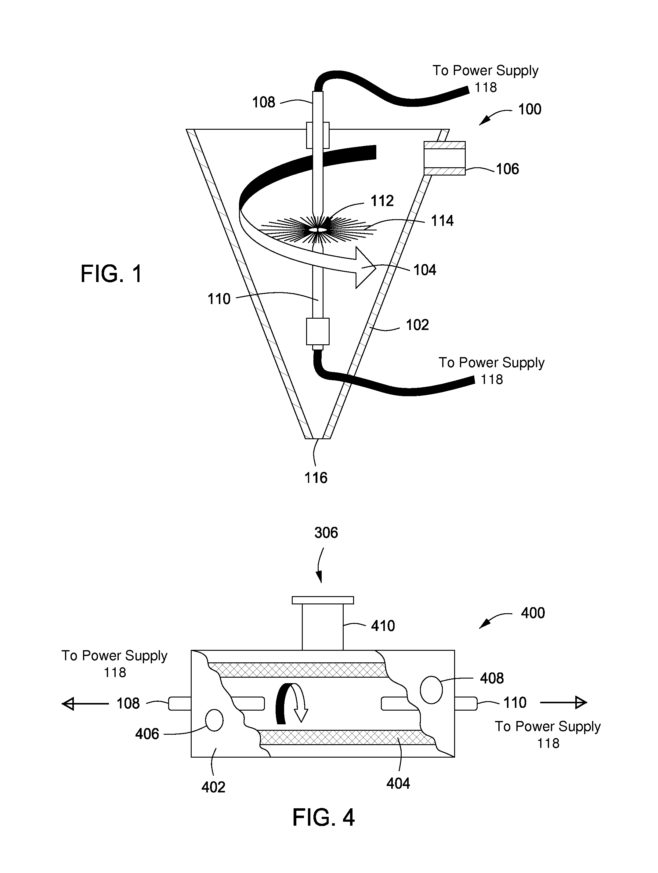
[0057]Now referring to FIG. 2, an Arc Whirl® cyclone separator 200 in accordance with the present invention is illustrated. A cyclone separator 202 can easily be modified for the present invention. The carbon rods 108 and 110 are inserted in the underflow 204 and overflow 206 of the cyclone separator 200. The substance is introduced into the cyclone separator 202 via inlet 208. The carbon arc is formed between the rods 108 and 110 within the core of the cyclone separator 202 when the carbon rods 108 and 110 are connected to power supply 118.

third embodiment

[0058]Referring now to FIG. 3, an Arc Whirl® gas-sparged hydrocyclone 300 in accordance with the present invention is illustrated. A hydrocyclone with a porous wall 304, referred to as an air-sparged hydrocyclone, can be used as the vessel 302 for the present invention. The carbon rods 108 and 110 are inserted in the underflow 204 and overflow 206 of the gas-sparged hydrocyclone 300. The substance is introduced into the vessel 302 via inlet 208. The carbon arc is formed between the rods 108 and 110 within the core of the vessel 302 when the rods 108 and 110 are connected to power supply 118. Air or gas 306 is introduced into the vessel 302 via gas inlet 308 connected to the porous wall 304. The air / gas sparged hydrocyclone 300 aids in stripping volatiles from the fluid and induce cavitation, in addition to the creation of a thin fluid film. Air-sparged hydrocyclones 300 can strip hydroscopic molecules, such as alcohols, from water. Further, the air boundary layer between the spargin...

fourth embodiment

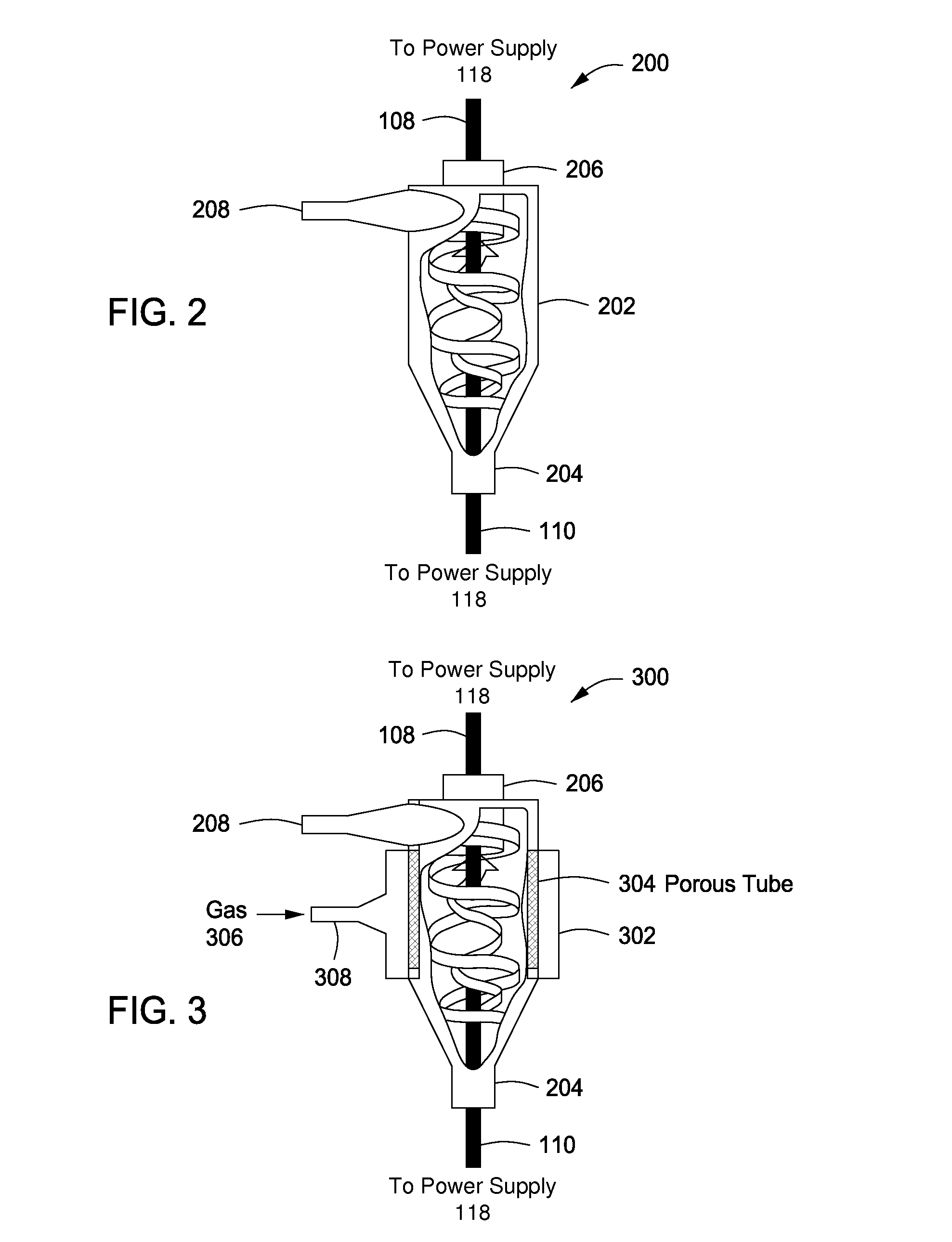
[0062]Now referring to FIG. 4, an Arc Whirl® gas-sparged pipe with tangential flow 400 in accordance with the present invention is illustrated. A pipe 402 with porous wall 404 can also be used for the present invention. The carbon rods 108 and 110 are inserted in each end of the pipe 402. The substance is introduced into the pipe 402 via inlet 406 and allowed to exit via outlet 408. The carbon arc is formed between the rods 108 and 110 within the core of the vessel 402 when rods 108 and 110 are connected to power supply 118. Air or gas 306 is introduced into the vessel 402 via gas inlet 410.


PUM

PropertyMeasurementUnit
distanceaaaaaaaaaa
distanceaaaaaaaaaa
depthaaaaaaaaaa

Abstract

A system for treating a substance using a storage vessel and two or more devices disposed in a top of the storage vessel. Each device has: (a) a volute or cyclone head, (b) a throat connected to the volute or cyclone head, (c) a parabolic reflector connected to the throat, (d) a first wave energy source comprising a first electrode within the volute or cyclone head that extends through the outlet into the opening of the throat along the central axis, and a second electrode extending into the parabolic reflector and spaced apart and axially aligned with first electrode, and (e) a second wave energy source disposed inside the throat, embedded within the throat or disposed around the throat. The substance is supplied to the inlet of the volute or cyclone head and is irradiated with one or more wave energies produced by the first and second wave energy sources.

Description

PRIORITY CLAIM AND CROSS-REFERENCE TO RELATED APPLICATIONS[0001]This patent application is a continuation-in-part application of both U.S. patent application Ser. No. 12 / 949,745 filed on Nov. 18, 2010 and entitled “System for Treating Fluids with Wave Energy from an Electrical Arc” and U.S. patent application Ser. No. 12 / 577,130 filed on Oct. 9, 2009 and entitled “Plasma Whirl Reactor Apparatus and Methods of Use.”[0002]U.S. patent application Ser. No. 12 / 949,745 is a divisional application of U.S. patent application Ser. No. 11 / 784,326 filed on Apr. 5, 2007 and entitled “System, Method and Apparatus for Treating Fluids with Wave Energy from an Electrical Arc”, now U.S. Pat. No. 7,857,972, which is: (a) a continuation-in-part application of U.S. patent application Ser. No. 10 / 935,786 filed on Sep. 7, 2004 and entitled “Treatment of Fluids with Wave Energy from a Carbon Arc”, now U.S. Pat. No. 7,422,695, which is a non-provisional application of U.S. provisional patent application 60...

Claims


Application Information

Patent Timeline
Patent Type & Authority Applications(United States)
IPC IPC(8): B01J19/08B01J19/10B01J19/12C25B9/18
CPCA23B4/015B01D2259/816A23L3/26B01J19/008B01J19/08B01J19/088B01J19/123B01J19/128B01J19/2405B01J19/247B01J2219/0809B01J2219/083B01J2219/0839B01J2219/0869B01J2219/0877B01J2219/0884B01J2219/185B01J2219/1946C02F1/006C02F1/20C02F1/30C02F1/302C02F1/32C02F1/34C02F1/4608C02F1/46104C02F2001/46152C02F2103/008C02F2103/16C02F2103/22C02F2201/009C02F2201/3228C02F2301/024C02F2301/026C02F2303/04C02F2305/023C02F2305/10B01D53/007B01J19/10C02F1/36C02F1/48B01D53/32B01D2257/91B01D2258/06B01D2259/802B01D2259/804B01D2259/806A23L2/50Y02W10/37Y02A20/212A23C3/07A23C3/073A23C3/076A23V2002/00B01D2259/81B01J19/12B01J19/126B01J19/129B01J2219/0875B01J2219/0894B01J2219/12C02F1/307C02F1/46109C02F2001/46133C02F2103/14C02F2103/32C02F2103/365
Inventor FORET, TODD
Owner FORET PLASMA LABS
Why Eureka
Try Eureka