Photovoltaic device and method for manufacturing the same
a photovoltaic device and crystal thin film technology, applied in semiconductor/solid-state device manufacturing, semiconductor devices, electrical devices, etc., can solve the problems of low crystal quality, low crystal quality, and waste of expensive wafers, so as to improve the collection efficiency of photogenerated carriers, and improve the photoelectric conversion characteristics
- Summary
- Abstract
- Description
- Claims
- Application Information
AI Technical Summary
Benefits of technology
Problems solved by technology
Method used
Image
Examples
embodiment mode 1
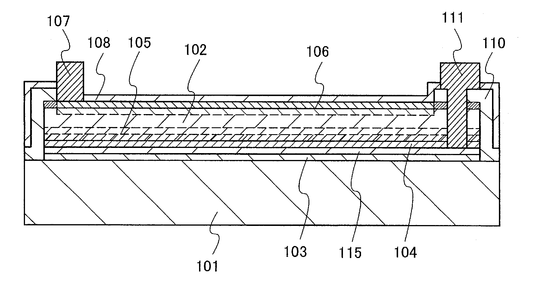
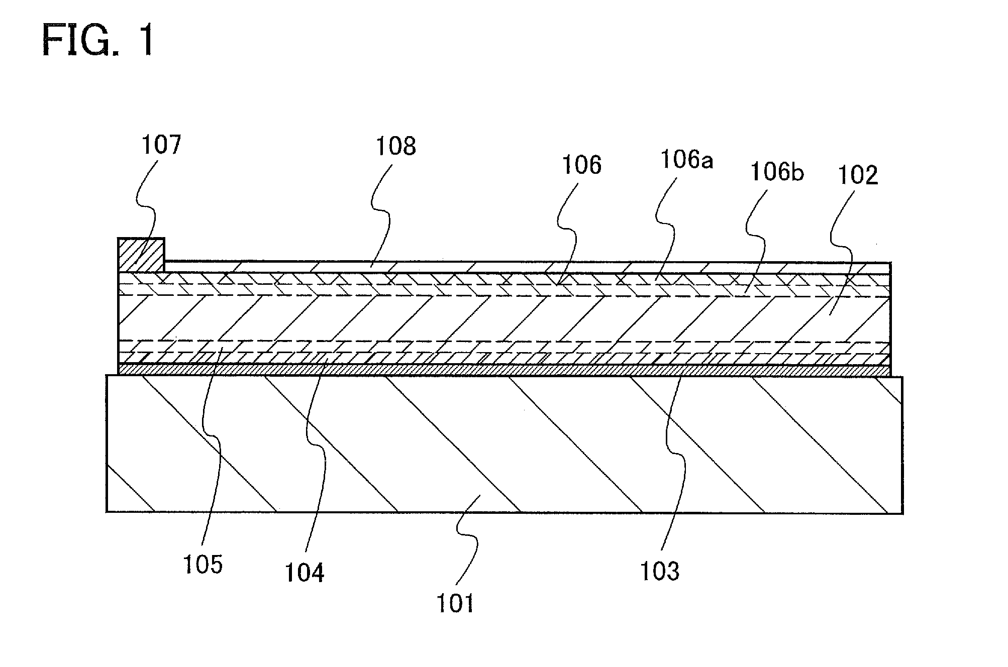
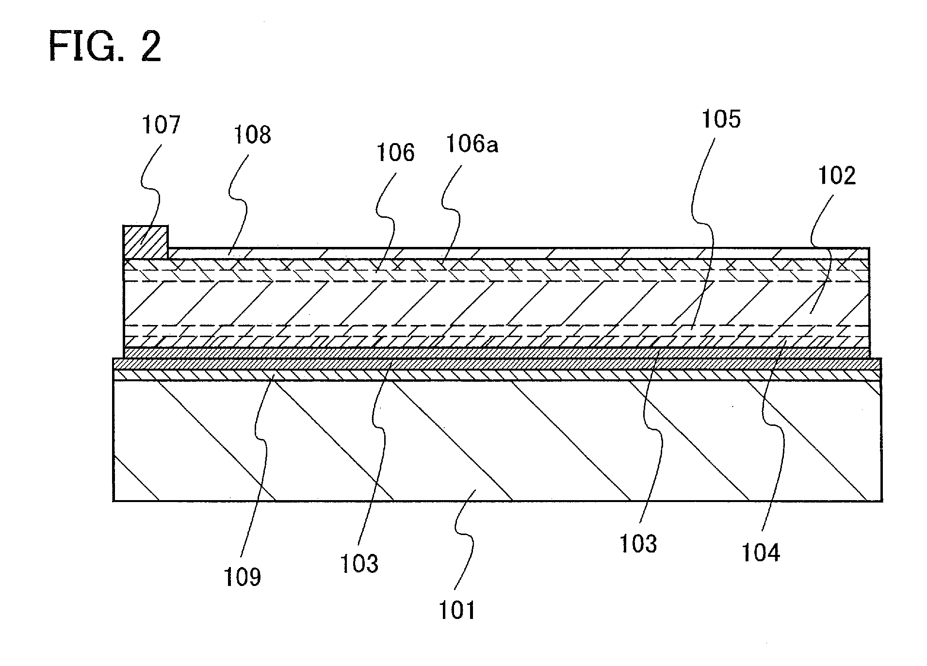
[0056]A method for manufacturing a photovoltaic device, in which a thin single crystal semiconductor layer is separated from a single crystal semiconductor substrate and the separated single crystal semiconductor layer is transferred to a substrate having an insulating surface or an insulating substrate, is described with reference to the drawings.
[0057]FIG. 4 is a plan view of a photovoltaic device relating to this embodiment mode. This photovoltaic device has a structure in which light is incident on the semiconductor layer 102 side provided over the substrate 101. In a peripheral portion of the substrate 101, an insulating layer 110 having an opening is provided over the semiconductor layer 102. The second electrode 107 having a comb shape is formed over the semiconductor layer 102. An extraction electrode 111 which is on a side opposite to the second electrode 107 is electrically connected to a first electrode through a contact hole penetrating the insulating layer 110 and the s...
embodiment mode 2
[0077]This embodiment mode describes an example of a method for providing a single crystal semiconductor layer over a large-area substrate and manufacturing a photovoltaic device module. Manufacturing steps of a photovoltaic device is similar to those illustrated in FIGS. 5A to 8C.
[0078]The single crystal semiconductor substrate 112 which is manufactured through the steps in FIGS. 5A to 5D is bonded to the substrate 101. Here, a substrate having an area to which a plurality of the single crystal semiconductor substrates 112 can be bonded is used as the substrate 101. The single crystal semiconductor substrate 112 is fixed to the substrate 101 with the bonding layer 103. A plurality of the single crystal semiconductor substrates 112 are fixed to the substrate 101, and then thermal treatment may be performed thereon to form a bond. When the single crystal semiconductor substrates 112 are separated, the semiconductor layer 102 is disposed over the substrate 101. FIG. 11 shows a state i...
embodiment mode 3
[0083]This embodiment mode describes manufacturing steps for manufacturing a photovoltaic device as described in Embodiment Mode 1, by reusing the single crystal semiconductor substrate 112 from which the semiconductor layer 102 has been taken out.
[0084]FIG. 17A shows a step in which the surface protection film 113 is formed over the single crystal semiconductor substrate 112 which has been used for forming the semiconductor layer 102 in Embodiment Mode 1, and the separation layer 114 is formed by introducing ions of hydrogen or halogen typified by fluorine. Ions of a rare gas such as helium, argon, or krypton may be added to the separation layer 114. The wide band-gap layer 116 remains on a surface side in the single crystal semiconductor substrate 112. The wide band-gap layer 116 is a layer which has been formed as a separation layer in a previous process and which includes hydrogen or halogen which remains in this process. In this process, a surface of the single crystal semicond...
PUM
 Abstract
Description
Claims
Application Information
 - R&D
- Intellectual Property
- Life Sciences
- Materials
- Tech Scout
- Unparalleled Data Quality
- Higher Quality Content
- 60% Fewer Hallucinations
Browse by: Latest US Patents, China's latest patents, Technical Efficacy Thesaurus, Application Domain, Technology Topic, Popular Technical Reports.
© 2025 PatSnap. All rights reserved.Legal|Privacy policy|Modern Slavery Act Transparency Statement|Sitemap|About US| Contact US: help@patsnap.com


