Three-dimensional optical coherence tomography confocal imaging apparatus

a confocal imaging technology, applied in the field of three-dimensional optical coherence tomography (3d oct) confocal imaging apparatus, can solve the problems of confocal microscope, uneasy to show the image quickly, chemical changes in the sample, etc., and achieve the effect of convenient us

Active Publication Date: 2011-12-22
NAT TAIWAN UNIV
View PDF8 Cites 52 Cited by
  • Summary
  • Abstract
  • Description
  • Claims
  • Application Information

AI Technical Summary

Benefits of technology

[0020](2) With the present invention, it is possible to obtain a sample's microscopic images and generate synchronized coherence confocal image electric signal for tr

Problems solved by technology

However, the transmission electron microscope would disadvantageously cause chemical changes in the sample; and electron beams illuminating the samples tend to destroy organic materials, molecular structures, DNA, etc.
However, the confocal microscope has a main disadvantage of uneasy to show the image quickly.
When the confocal microscope is applied in the study of biofilm, collagen protein, cell movement, liquid interface or liquid-gas interface characteristics and the like, there would be considerable limitation.
Moreover, the confocal microscope has a resoluti

Method used


Image

  • Three-dimensional optical coherence tomography confocal imaging apparatus
  • Three-dimensional optical coherence tomography confocal imaging apparatus
  • Three-dimensional optical coherence tomography confocal imaging apparatus

Examples


first embodiment

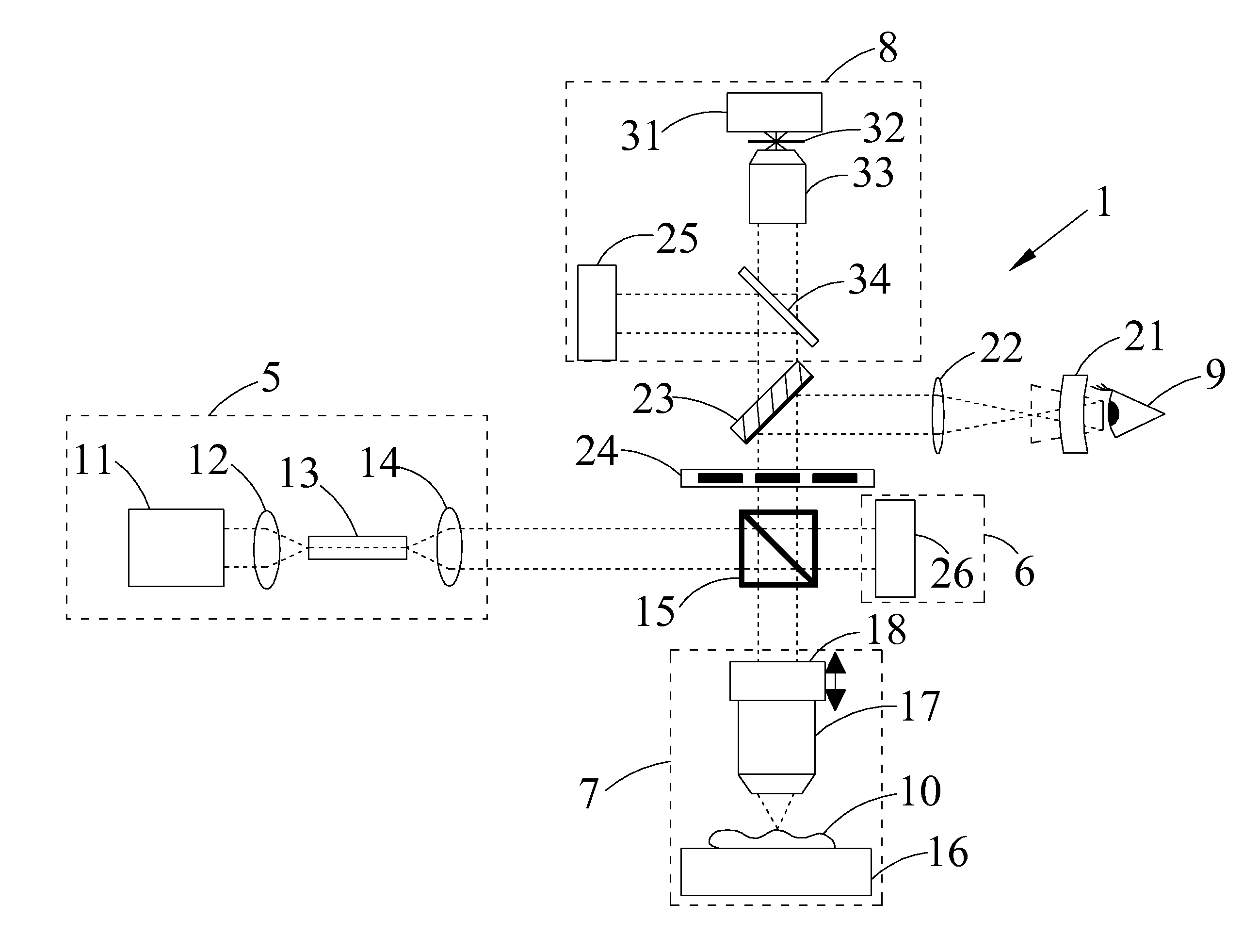
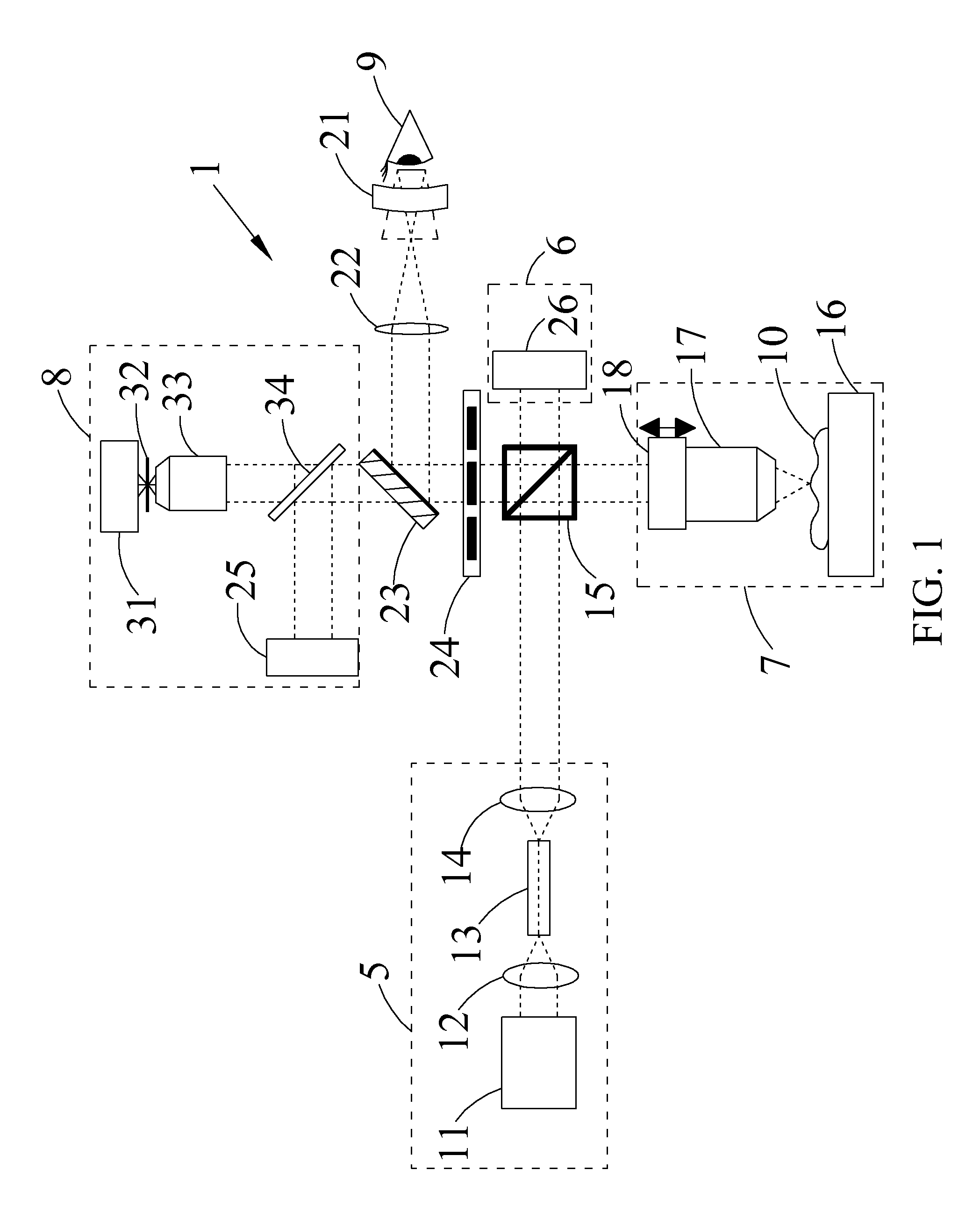
[0032]Please refer to FIG. 1, which is a schematic diagram of a 3D OCT confocal imaging apparatus 1 according to the present invention. The 3D OCT confocal imaging apparatus 1 shown in FIG. 1 is used to produce the microscopic images of the sample 10 at different depths. Via an externally connected image processing computer (not shown), image electric signals converted from the microscopic images can be processed to form a three-dimensional visualized image of the sample 10. As shown in FIG. 1, the 3D OCT confocal imaging apparatus 1 includes a pumping source module 5, a reference source module 6, a pickup module 7, a beam splitter 15, an optical filter 24, and a sensor module 8.

[0033]The light source module 5 includes a pumping laser source 11, a focusing lens 12, a broadband gain medium 13, and a collimator 14. The pumping laser source 11 can be either a diode laser or a solid laser capable of emitting laser light when being excited, and the emitted laser light usually has a relat...

second embodiment

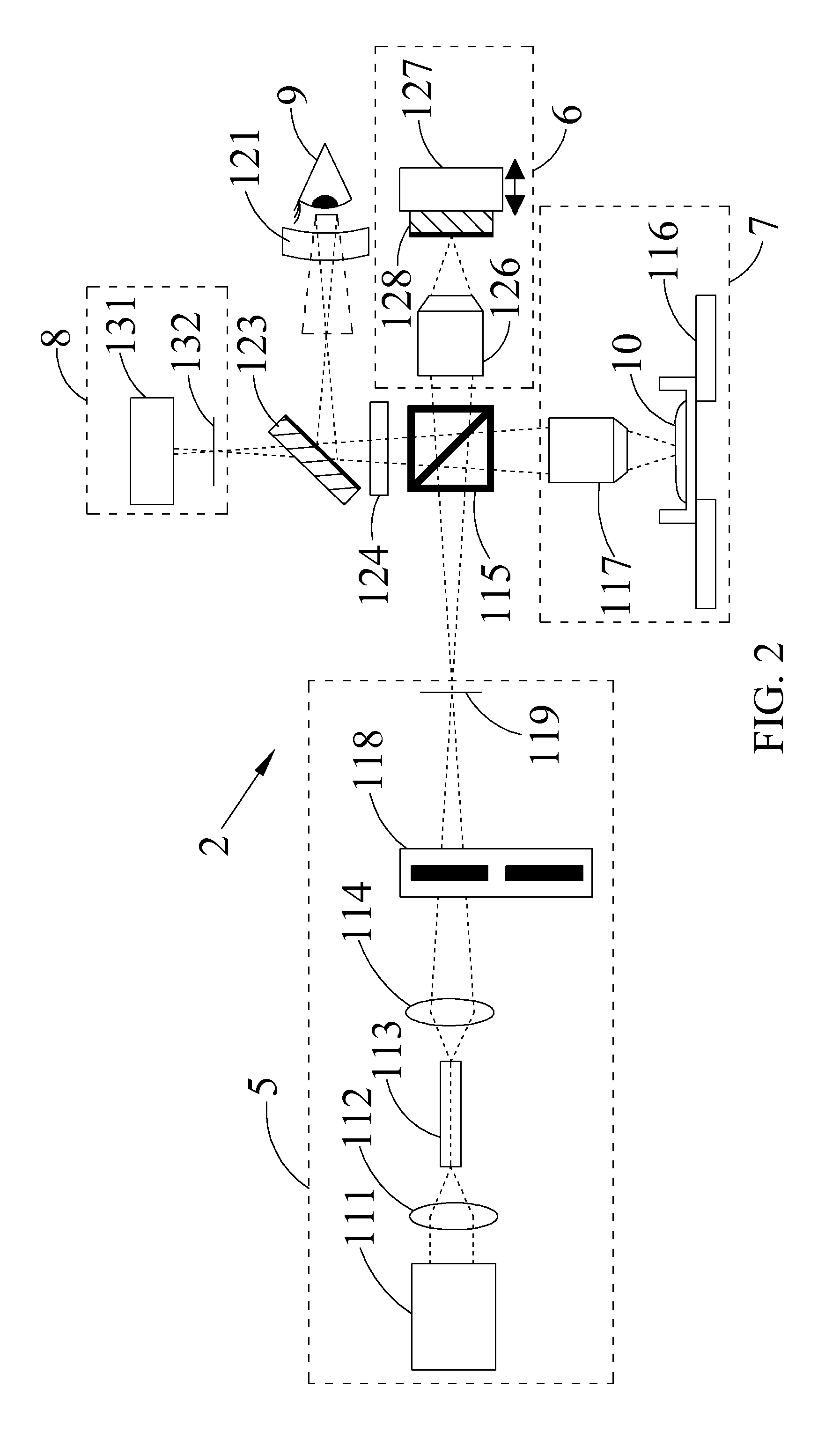
[0052]As in the second embodiment, to observe the focusing condition of the sample 10, an observer 9 can insert a slit mirror 223 into the optical path. Being reflected by the slit mirror 223, the image beam passes through an eye piece 221 and is observed by the observer 9.

[0053]The sensor module 8 includes a photosensor 225. The photosensor 225 is adapted to convert the interference image into a coherence image electric signal for transmitting outward. Similarly, with the above arrangements, when the pickup module 7 has picked up the images of the sample 10 laterally and in depth, a 3D microscopic image of the sample 10 can be formed from the correspondingly generated coherence image electric signals.

third embodiment

[0054]To observe the confocal fluorescence microscopic imaging, a coupled confocal fluorescence microscopic imaging module 20 can be arranged below the sample 10 at an opposite side of the pickup module 7 for generating a coupled confocal fluorescence image electric signal. The coupled confocal fluorescence microscopic imaging module 20 includes a second pickup objective lens 234, a second mirror 235, a second piezoelectric actuator 237, a band wavelength pass filter (BWP) 236, a second confocal objective lens 233, a second pinhole 232, and a fluorescence sensor 231. When the illumination beam illuminates the sample 10, the second pickup objective lens 234 adjusts the focal point of the image of the sample 10 below the sample 10, so as to produce a second image beam. Generally, the second pickup objective lens 234 is a high NA objective lens in order to push up the axial resolution of confocal image. In the illustrated third embodiment, the reference objective lens 226 is a low NA o...


PUM


Abstract

A 3D OCT confocal imaging apparatus includes a light source module for providing an illumination beam with wider bandwidth from a crystal fiber; a reference source module; a pickup module; a beam splitter; an optical filter; and a sensor module. When the illumination beam illuminates a sample, a pickup objective lens and a piezoelectric actuator of the pickup module together provide an image beam scanning the sample in depth direction. The image beam and a reference beam from the reference source module together form an interference image beam, which is converted by a photosensor into a coherence image electric signal. Meanwhile, the interference image beam passes through a pinhole to form a confocal image, which is converted by an excited light photometer into a confocal image electric signal. With an image processing system, a 3D OCT confocal microscopic image of the sample can be produced from these image electric signals.

Description

FIELD OF THE INVENTION[0001]The present invention relates to a three-dimensional optical coherence tomography (3D OCT) confocal imaging apparatus, and more particularly to a 3D microscope for forming optical coherence tomography images and confocal microscopic images.BACKGROUND OF THE INVENTION[0002]In early stage, microscopic technology is realized mainly by electron microscope and optical microscope. An optical microscope uses optical lenses to magnify images of a sample to reach a resolution up to 200 nm. On the other hand, an electron microscope utilizes the short wavelength characteristic of electrons to observe micro crystal structure or biological cellular structure. In the case of a transmission electron microscope, a resolution up to 0.1 nm can be reached. However, the transmission electron microscope would disadvantageously cause chemical changes in the sample; and electron beams illuminating the samples tend to destroy organic materials, molecular structures, DNA, etc.[00...

Claims


Application Information

Patent Timeline
IPC IPC(8): G01B9/02
CPCG01B9/02091G01B2290/45G01B9/02042G01B9/02005
Inventor TSAI, CHIEN-CHUNGHSU, KUANG-YULIN, YEN-SHENGHUANG, SHENG-LUNG
Owner NAT TAIWAN UNIV
Why Eureka
Try Eureka