Electrical energy storage device

a technology of energy storage device and energy storage device, which is applied in the direction of hermetically sealed casings, sustainable manufacturing/processing, and wound/folded electrode electrodes. it can solve the problems of increasing the entire internal electrical equivalent resistance, not easy to connect the terminal plate, and affecting the resistance and efficiency of the secondary battery, so as to improve the efficiency of high-rate discharge (large current discharge) and reduce the thickness differen

Inactive Publication Date: 2011-12-29
MAXWELL TECH KOREA CO LTD
View PDF4 Cites 38 Cited by
  • Summary
  • Abstract
  • Description
  • Claims
  • Application Information

AI Technical Summary

Benefits of technology

[0022]According to the electrical energy storage device of the present invention, in which an interconnecting member for reducing a difference in thickness between objects to be welded is employed, it is possible to prevent welding failure between polarity-leads of an electrode winding body and a terminal plate and, at the same time, extend the welding range, thereby improving high-rate discharge (large current discharge) efficiency.
[0023]In other words, the internal equivalent resistance is reduced, which improves the discharge characteristics during high-rate discharge, and thereby the discharge efficiency during large current discharge is improved.

Problems solved by technology

As a result, such connection methods significantly affect not only resistance and efficiency of the secondary battery, but also productivity of the secondary battery itself and use convenience thereof.
First, it is not easy to connect the terminal plate 20 of the electrical energy storage device to the polarity-leads A and B of the electrode winding body.
Moreover, the welding or soldering may cause a contact failure between the polarity-leads A and B and an interconnecting member 40, which increases the entire internal electrical equivalent resistance.
Therefore, when the lead connection parts of the electrode winding body having a very small thickness and the terminal plate having a large thickness are directly joined together by laser welding, there is a significant difference in thermal effects between the terminal plate and the lead connection parts, and thus the welding is not properly performed.
In this method, the friction on the bonding surfaces caused by the vibration destroys any oxide film on the surfaces and causes local plastic deformation such that newly exposed metal surfaces are closely adhered to each other.
Moreover, a local increase in temperature caused by the frictional heat accelerates diffusion and re-crystallization of atoms, which results in the formation of a strong pressure-welded portion.
However, when the leads of the electrode winding body having a very small thickness are directly ultrasonic-welded to the terminal plate having a large thickness, there is a significant difference in thermal effects between the terminal plate and the leads, and thus the welding is not properly performed
As a result, the welding may not be properly performed or the objects may be excessively melted.
The improper welding increases the internal resistance of a capacitor, and when the objects are excessively melted, the insulating paper may be burned to cause an insulation failure between the two electrodes.

Method used


Image

  • Electrical energy storage device
  • Electrical energy storage device
  • Electrical energy storage device

Examples


Embodiment Construction

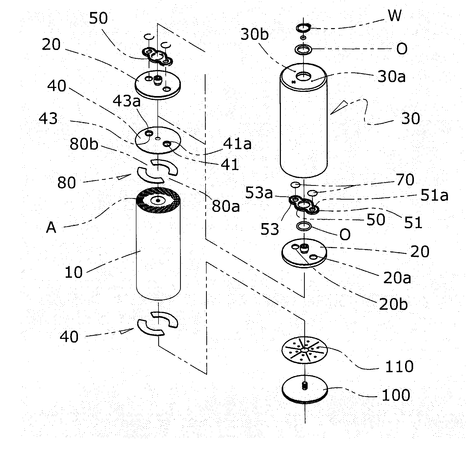
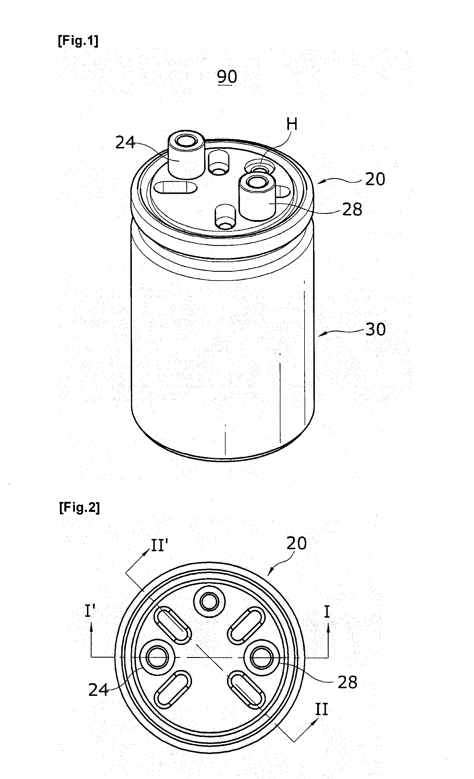
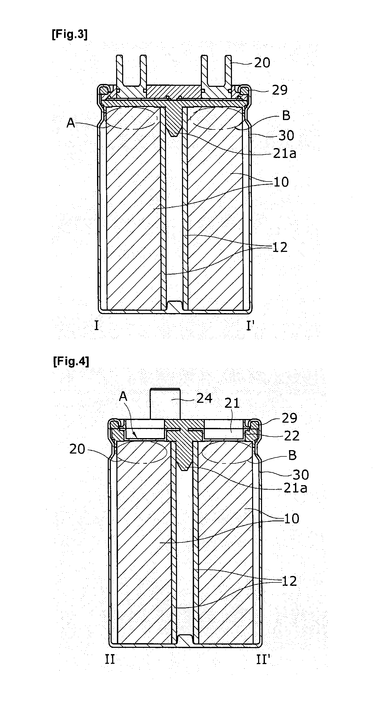
[0039]Hereinafter, the construction of the present invention will be described with reference to the attached drawings. FIG. 6 is a perspective view of an electrical energy storage device having bidirectional terminals in accordance with an exemplary embodiment of the present invention, FIG. 7 is a plan view and a side view of the electrical energy storage device shown in FIG. 6, FIG. 8 is a longitudinal cross-sectional view taken along the line A-A of the electrical energy storage device shown in FIG. 7, FIG. 9 is an exploded perspective view of the internal components of the electrical energy storage device shown in FIG. 6, FIG. 10 is an exploded perspective view showing an interconnecting member and a sealing member of the electrical energy storage device shown in FIG. 9 in accordance with an exemplary embodiment of the present invention, FIG. 11 is an exploded perspective view showing an interconnecting member and a sealing member of the electrical energy storage device shown in...


PUM

PropertyMeasurementUnit
thicknessaaaaaaaaaa
thicknessaaaaaaaaaa
thicknessaaaaaaaaaa

Abstract

Provided is an electrical energy storage device including an electrode winding body, which includes a positive electrode generating electrons by oxidation and reduction, a negative electrode for absorbing the generated electrons, and separation layers for physically separating the negative electrode from the positive electrode, which are sequentially wound around a winding core, and an electrolyte provided between the positive electrode and the negative electrode, the electrical energy storage device including: a terminal plate for externally connecting the electrode winding body to an external electrode connecting member such as an external resistor; a cylindrical can for accommodating the electrode winding body connected to the terminal plate; and a conductive interconnecting member for connection between the terminal plate and polarity-leads on one side of the electrode winding body by a method selected from the group consisting of plasma-spraying, welding, soldering and adhesion using a conductive adhesive material. According to the present invention, in which an interconnecting member for reducing a difference in thickness between objects to be welded is employed, it is possible to prevent welding failure between the polarity-leads of the electrode winding body and the terminal plate, thereby improving high-rate discharge (large current discharge) efficiency.

Description

TECHNICAL FIELD [0001]The present invention relates to an electrical energy storage device, and more particularly, to a cylindrical electrical energy storage device which can reduce error rate and internal equivalent resistance and improve high-rate discharge efficiency when a terminal plate and polarity-leads of an electrode winding body are joined together.BACKGROUND ART [0002]In comparison with a primary battery having a discharge function only, a secondary battery such as a capacitor having both charge and discharge functions is fabricated by various methods for electrically connecting an internal current source to an external resistor. As a result, such connection methods significantly affect not only resistance and efficiency of the secondary battery, but also productivity of the secondary battery itself and use convenience thereof.[0003]Therefore, there is a strong need for a terminal connection method capable of increasing electric capacity and reducing internal resistance, ...

Claims


Application Information

Patent Timeline
Patent Type & Authority Applications(United States)
IPC IPC(8): H01G9/10H01G9/145H01M50/503H01M50/517H01M50/536H01M50/538H01M50/55H01M50/559H01M50/566
CPCH01G2/04H01G4/232Y02E60/12H01M2/30H01M10/0431H01M2/202H01M10/0422Y02E60/10H01M50/538Y02P70/50H01M50/559H01M50/55H01M50/536H01M50/517H01M50/503H01M50/566H01M50/50
Inventor CHUN, KYUNG-SANGJEONG, KWAN-GU
Owner MAXWELL TECH KOREA CO LTD
Why Eureka
Try Eureka